Chapter 5 UCM communication link wiring and topology
48 BMTX-SVN01C-EN
Resistance termination for Comm5 links
To correctly install a Comm5 link, termination resistors are required at
the first and last devices on each link. Electrical resistors drop the voltage
of the current flowing through the wire so that electrical noise is
absorbed. See Table 7 to determine how much resistance is needed.
For correct termination placement, follow these guidelines:
• Terminate a daisy-chain configuration with a resistor at each end of
the link. See Table 7 for resistance requirements.
• If a repeater is used, each link of the configuration that is created by
the repeater requires termination resistors (see “Comm5 repeater” on
page 48 and Figure 23 on page 46).
• Trane recommends that only one type of wire be used for the Comm5
communication link.
• A set of as-built drawings or a map of the communication wire layout
should be made during installation. Any sketch of the communication
layout should feature the termination resistor placement.
Comm5 repeater
The Comm5 repeater is a device that repeats and regenerates the signal
on a Comm5 link. The Comm5 link goes from the BCU to the repeater
and a second link segment extends from the other side of the repeater to
the rest of the UCMs. The configurations on either side of the repeater
should be daisy-chained. Both link segments require proper termination
(see “Resistance termination for Comm5 links” on page 48).
When is the repeater required?
If any one of the following conditions exists, a repeater is required:
• If the total wire length is greater than the maximum wire run length
of 4,500 ft (1,400 m).
• If more than 60 devices are connected to a link. This total does not
include the BCU, the repeater, and the temporary use of the Rover
service tool on the same link.
• If more than eight zone sensor communication stubs are required on a
Comm5 link (see “Zone sensor communication stubs on Comm5 links”
on page 53).
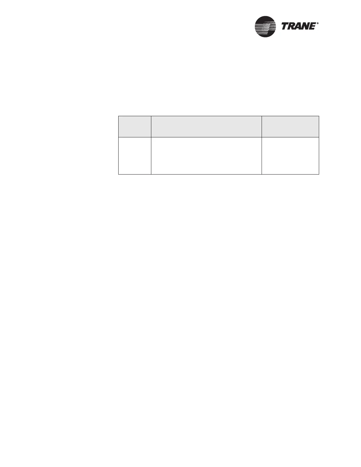
Table 7. Termination resistor placement for Comm5 links
Wire
length
Resistance Resistor placement
Any
• 105 Ω, for sites using the recom-
mended 22-gauge, Level 4 wire.
• 82 Ω, for existing sites already wired
with 18-gauge Trane-approved, purple-
jacketed wire.
At each end of link
 Loading...


