Chapter 2 Modem installation
14 BMTX-SVN01C-EN
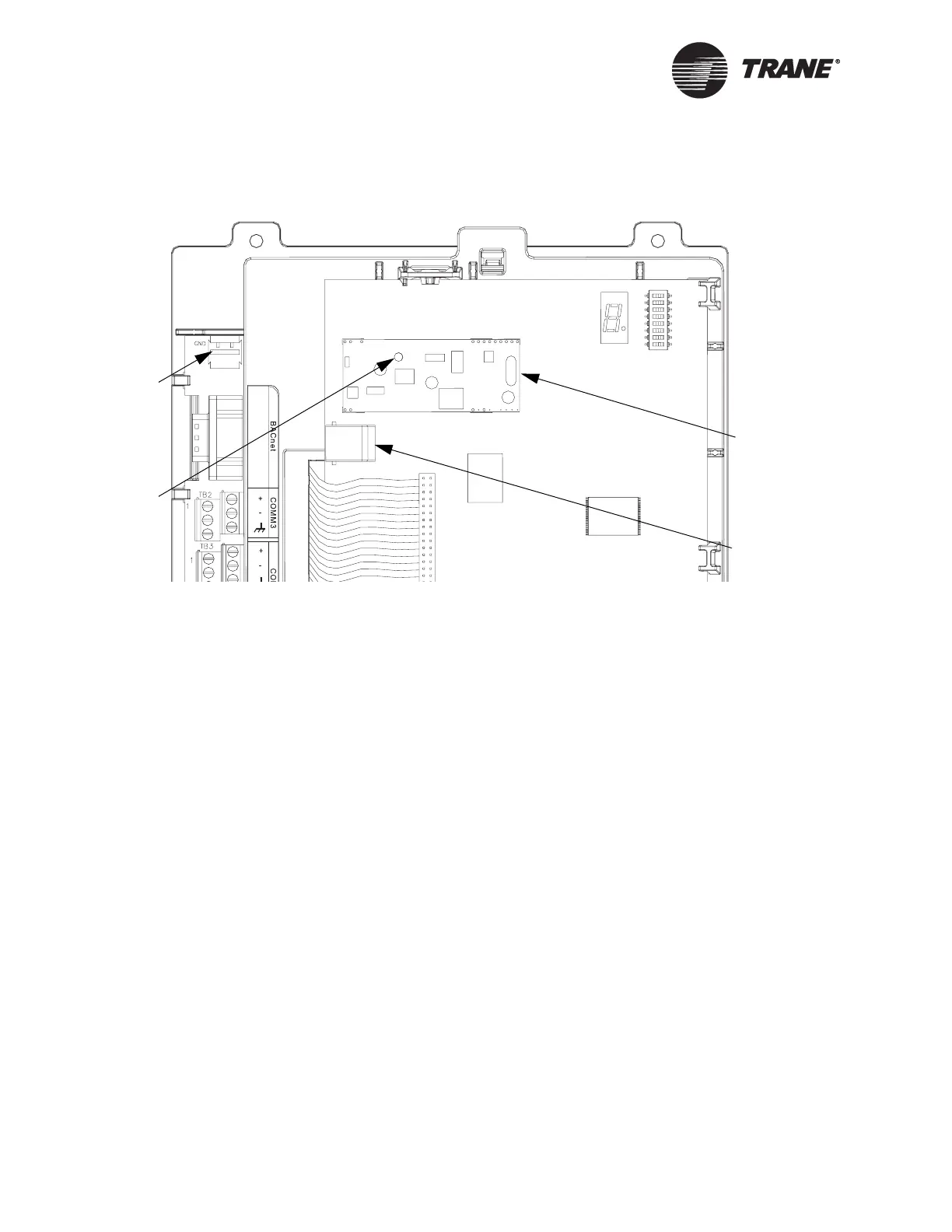
Figure 4. BMTX BCU with modem installed on 120 V system
Installing the modem on 230 V systems
(international)
Install the modem as follows (see Figure 5 on page 15 and Figure 6 on
page 16):
1. If connected, disconnect the 24 Vac power cable from the termination
board.
2. Remove the main circuit board by using a small, blunt object, such as
a screw driver or pen, to push each of the mounting locks on the top
frame away from the circuit board. The board pops out. Lift the board
away from the frame.
3. Insert two of the modem cover screws into the back of the main circuit
board. Secure the screws by screwing the two stand-offs onto them.
4. Set the shield in place on the top frame.
5. Replace the main circuit board by pushing the circuit board and the
top frame together. You will hear a click when they lock together.
6. On the main circuit board, press the plastic spacer into the spacer
hole. You should hear the spacer snap into place.
7. Line up the spacer hole in the modem card with the spacer on the
main circuit board.
Termination board
Main circuit board
Spacer
Modem card
Modem, phone
line connector
24 Vac power
connector
 Loading...


