Installing the modem on 230 V systems (international)
BMTX-SVN01C-EN 15
8. Gently press the modem card down onto the spacer. Take care to line
up all the pins on both sides of the card.
Note: One pin on the card will not mate with a socket connection.
9. Line up the two holes on the modem cover with the stand-offs and
gently slide the cover down over them. Screw the other two modem
cover screws onto the stand-offs to secure the cover.
10. Connect the modular phone cable.
11. Connect the 24 Vac power cable to the termination board.
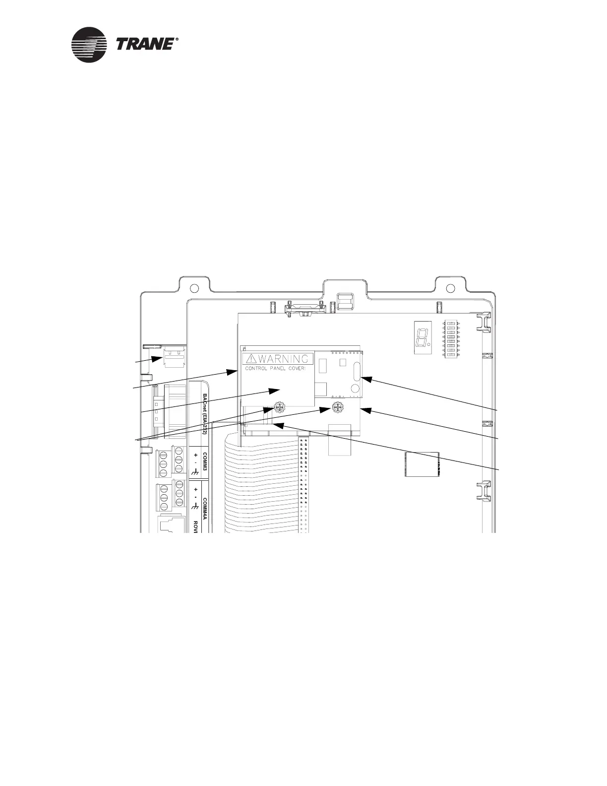
Figure 5. BMTX BCU with modem installed on 230 V system
Termination board
Main circuit board
Spacer
(not visible)
Modem card
24 Vac power
connector
Modem,
phone line
connector
Modem cover
Modem cover
screws
(2 visible, 2 not
visible)
two stand-offs
(not visible)
Shield
(not visible)
 Loading...


