Chapter 5 UCM communication link wiring and topology
40 BMTX-SVN01C-EN
Each fiber-optic port has two connections, one for transmitting informa-
tion and one for receiving information.
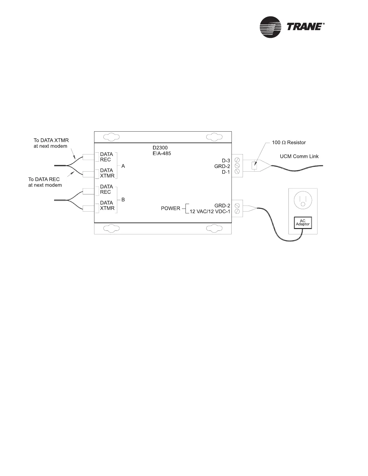
An illustration of a D2300 and the connections to it is provided in
Figure 20. The D1300 looks like the D2300 shown in this figure, but it has
only one fiber-optic port. The mounting and power wiring is the same for
both modems.
Figure 20. EIA-485 data repeater (D2300) fiber-optic modem
To mount and wire a D1300 and/or D2300 modems on an inter-building
communication link, follow these procedures (see Figure 21 on page 41):
1. In Building A, mount the modem on the wall using the four mounting
screw holes on the case.
2. Connect power to the modem using the ac adapter provided with the
modem. The adapter has two wires: one black with a white stripe, and
one solid black. The white striped wire connects to the 12 Vac/Vdc
connection on the modem, and the solid black wire connects to the
ground (GRD-2) terminal.
3. Verify that a proper connection is made by plugging the ac adapter
into an electrical outlet and viewing the red power LED on the left
side of the modem. If the red LED does not illuminate, check the
polarity of the connection and verify that the electrical outlet is pow-
ered.
4. Connect the UCM communication link and a termination resistor (if
needed) to the modem as shown in Figure 20 on page 40. Connect the
shield at the BCU end and tape it back at the modem end. Polarity of
this connection is important only for Comm4 cards.
Exception: In buildings that do not have a BCU, the shield from the
communication link wiring must be grounded on the GRD-2 terminal
between the two UCM communication link wire terminals of the
fiber-optic modem. The shield wire must not touch either of the two
communication wires.
 Loading...


