Comm3/Comm4 wiring
BMTX-SVN01C-EN 41
5. Connect the terminated fibers to the modem, one to DATA REC and
one to DATA XTMR.
6. In Building B, mount another modem on the wall using the four
mounting screw homes on the case.
7. Repeat steps 2 through 4.
8. Connect the terminated fibers that are connected to the modem in
Building A to DATA REC and DATA XTMR. Make sure that the fiber
going to DATA REC on the modem in the present building connects to
DATA XTMR on the modem in the next building. Keep track of the
polarity by recording the color of the jacket on each fiber and to which
connection it goes on each building.
IMPORTANT
Fiber-optic polarity is extremely important! Make sure that the fiber
connections on the fiber-optic modem are reversed at the next modem.
9. For each successive building to be wired on the communication link,
repeat steps 6 through 8.
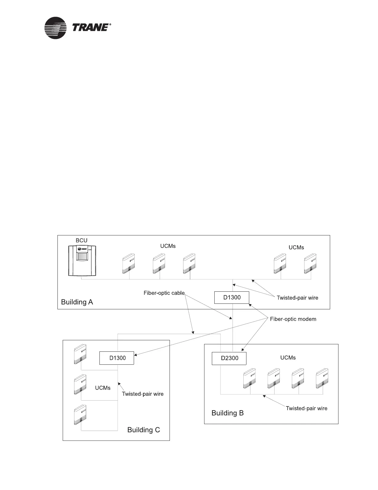
Figure 21. Typical example of inter-building fiber-optic cabling with
Comm3/4 communication
 Loading...


