Description of UCM types
BMTX-SVN01C-EN 59
• The CCP IIs software version is shown on the label of the chip at loca-
tion U-27 on the board. The revision level of the board determines
whether previous software versions of the CCP can be upgraded to be
compatible with a Tracer Summit system.
Wiring requirements
To establish wiring connections between the CCP II and the BMTX BCU,
refer to the specifications on wire type, topology, and wire procedures in “”
on page 34. Attach the communication link wiring to the CCP II at TB3-4
and TB3-5
Device addressing
Each CCP II must have a unique address on each link. CCPs can have an
address from 1 through 32. The address is set with the S2 DIP switches
and must match the address that was set in Site Configuration for Tracer
Summit.
• For details about setting the address, refer to the CCP II literature.
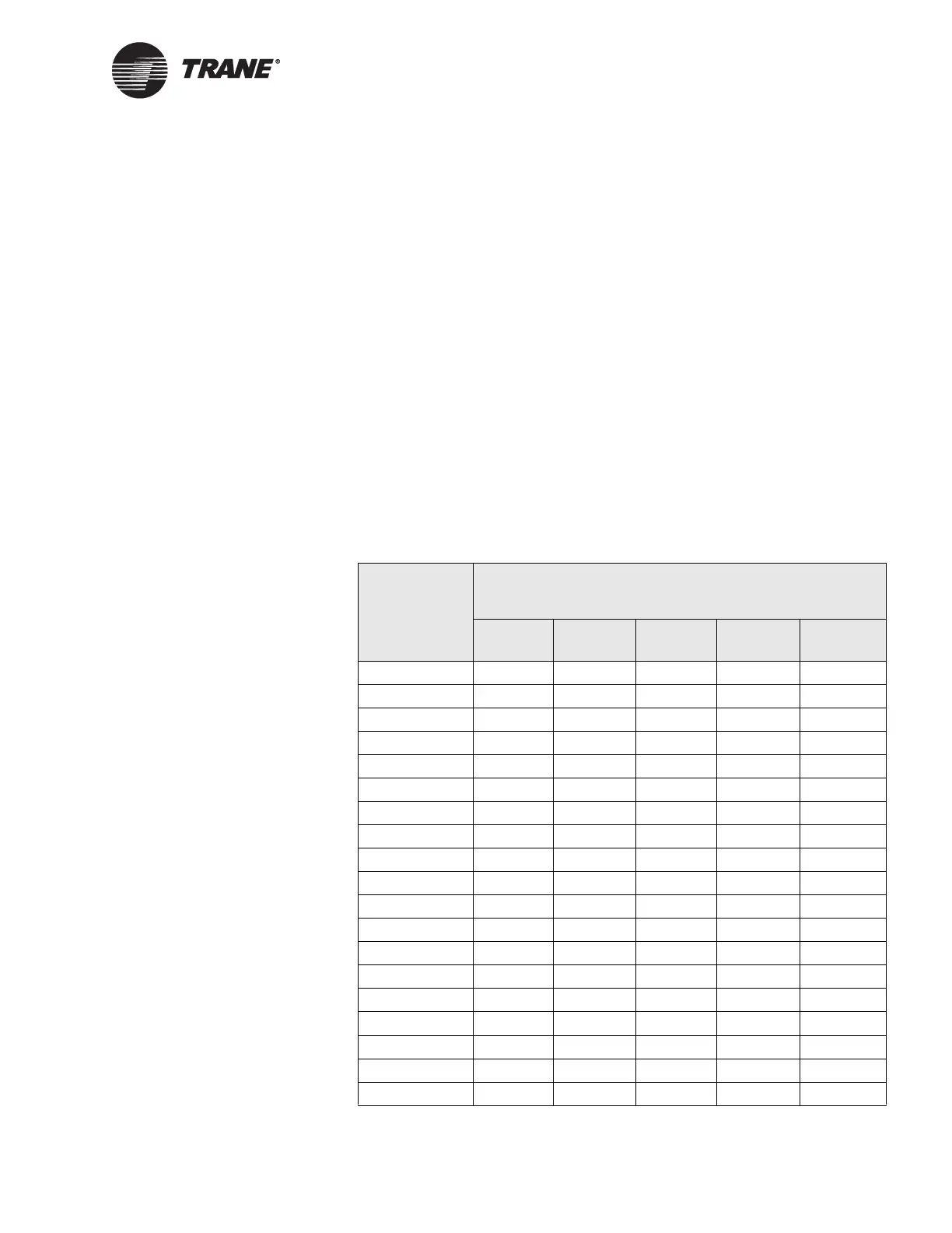
• For CCP II DIP switch settings, refer to Table 9.
Table 9. CCP II DIP switch settings
UCM address
CCP II
S2 DIP switch settings
1 2 3 4 5
1 on OFF OFF OFF OFF
2 OFF on OFF OFF OFF
3 on on OFF OFF OFF
4 OFF OFF on OFF OFF
5 on OFF on OFF OFF
6 OFF on on OFF OFF
7onononOFFOFF
8 OFF OFF OFF on OFF
9 on OFF OFF on OFF
10 OFF on OFF on OFF
11 on on OFF on OFF
12 OFF OFF on on OFF
13 on OFF on on OFF
14 OFF on on on OFF
15 on on on on OFF
16 OFF OFF OFF OFF on
17 on OFF OFF OFF on
18 OFF on OFF OFF on
19 on on OFF OFF on
 Loading...


