6
Curtis 1234/36/38 Manual, Rev. D
1 1 J U LY 2 0 0 8 D R A F T
2 — INSTALLATION & WIRING: High Current Connections
HIGH CURRENT CONNECTIONS
There are five high-current terminals, identified on the controller housing as
B+, B-, U, V, and W.
Table 1 High Current Connections
TERMINAL FUNCTION
B+ Positive battery to controller.
B- Negative battery to controller.
U Motor phase U.
V Motor phase V.
W Motor phase W.
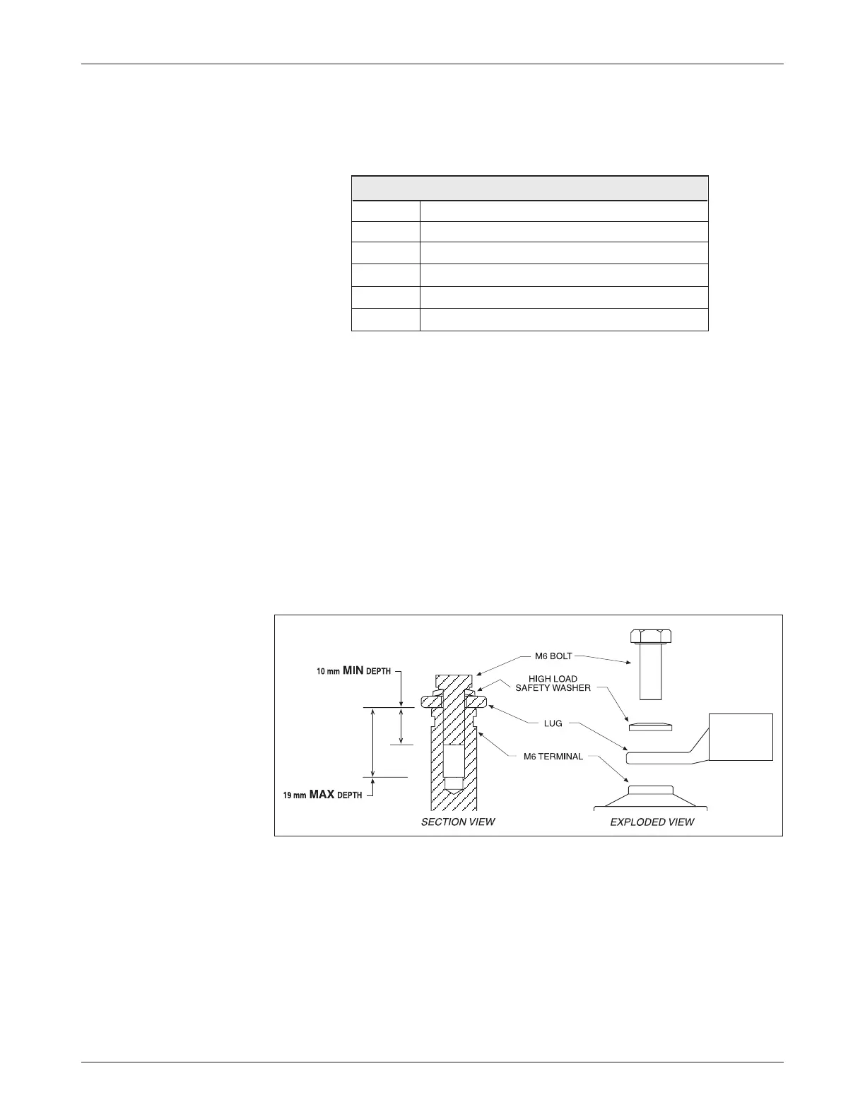
Lug assembly: 1234 models
Five aluminum M6 terminals are provided. Lugs should be installed as follows,
using M6 bolts sized to provide proper engagement (see diagram):
• Place the lug on top of the aluminum
terminal, followed by
a high-load safety washer with its convex side on top. The
washer should be a
SCHNORR 416320, or equivalent.
• If two lugs are used on the same
terminal, stack them so the
lug carrying the least current is on top.
• Tighten the assembly to 10.2 ±1.1 N·m (90 ±10 in-lbs).