D301087 0308 - BL20 CANopen 4-211
I/O-Module Objects
4
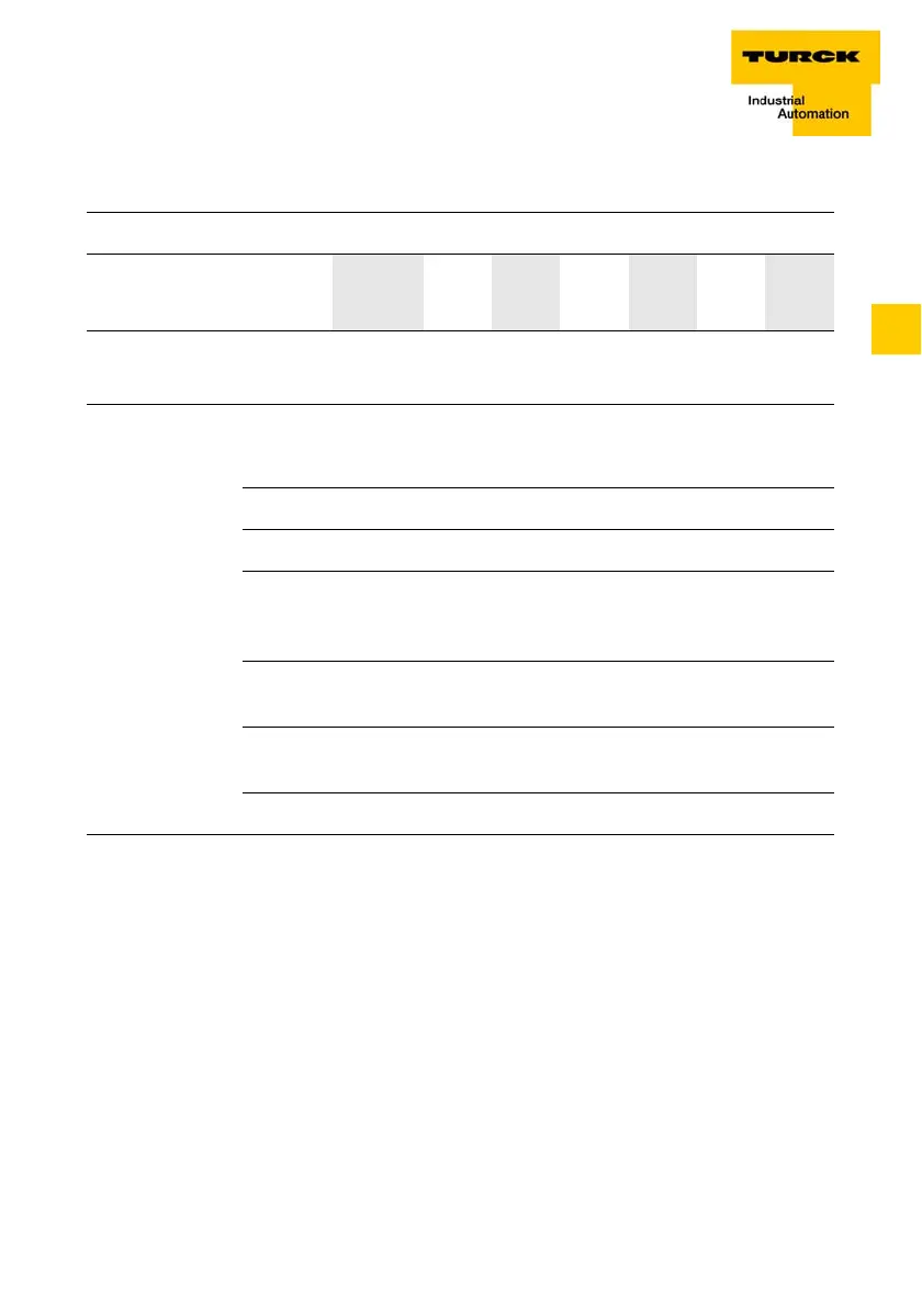
Structure of the data bytes in measurement mode:
X = reserved
Bit 7 Bit 6 Bit 5 Bit 4 Bit 3 Bit 2 Bit 1 Bit 0
Byte 0
(Status)
STS_
DN
STS_
UP
X XSTS_
DO1
XSTS_
DI
STS_
GATE
Table 145:
Meaning of the
status data bits
Designation Description
STS_DN 1: Status direction down.
STS_UP 1: Status direction up.
STS_DO2 Only count mode:
The DO2 status bit indicates the status of digital
output DO2.
STS_DO1 The DO1 status bit indicates the status of digital
output DO1.
STS_DI The DI status bit indicates the status of digital input
DI.
STS_GATE 1: Counting/measuring operation running.
 Loading...

