DocNo.FM0410issueM‐1Page11
6.NETWORKTERMINATIONBOARD
FIRE ALARM INPUT(issue “A-D” A00415 Amp Board & V1.0x Firmware)
When0Visappliedtoinput4a“999”firealarmcallwillbereportedviathecurrentoperatingmode.Ifinput4isstillactive
whenthiscallhasbeenansweredandclearedafiretonewillstarttosoundthroughallintercoms(unlessdisabledinthe
GeneralSet‐upprogramming).Thefiretonewillcontinueuntilinput4isremoved,i.e.whenthebuilding sFireAlarmPanel
isreset.Ifthesystemisoperatinginonsitemodeitispossibletostopthefiretoneandresumenormaloperationbefore
theFirePanelisresetbyliftingthehandsetandpressingthe“5”keyinthegapbetweentheburstsoftone.Thefirealarm
callwillnotre‐reportuntilthe0Vsignalisremovedandreappliedtoinput4.Note,thefiretonecannotbestopped(or
parked)viaLocalorRemoteOffsitemode‐theFireAlarmPanelmustbereset.Relayoutput2canbesettoenergisefor
thedurationinput4isapplied;thisisnormallyusedtooverridethemainentrancedoorelectriclockreleaseallowingthe
EmergencyServicestoenter.
FIRE ALARM INPUT(issue “E” A00415 Amp Board onwards & V2.0x Firmware onwards)
When0Visappliedtoinput4a“999”firealarmcallwillbereportedviathecurrentoperatingmodeandatthesametime
afiretonewillstarttosoundthroughallintercoms(unlessdisabledintheGeneralSet‐upprogramming).Thefiretonewill
continueuntilinput4isremoved,i.e.whenthebuildingsFireAlarmPanelisreset.AllotherFireAlarmrelatedfeaturesare
asV1.0describedabove.
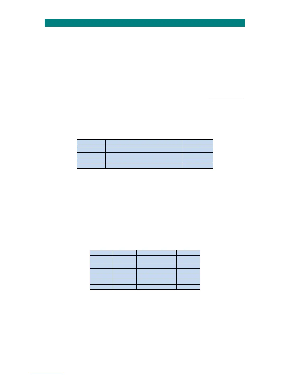
OUTPUTS
Thereare4N/Ocleancontactoutputswhichcanbeprogrammedforanumberoffunctions.Thecontactsareratedat24V
DC500mA.
OutputNo. Function CPULED
1 AnyAlarmOutputorDTMFRelay1 LED4
2 FireAlarmOutputorDTMFRelay2 LED5
3 BTLineSelectororDTMFRelay3 LED6
4 BTLineFaultorDTMFRelay4 LED7
WhenanoutputisactivatedtherelevantLED4‐7willilluminateonthemainCPUboard.
Note;alloutputscanbeactivatedwithDTMFkeysorsetassystemoutputs‐seetheAdventxtProgrammingManual
(TynetecDocNo.FM0411).
EXTERNAL PSU INPUT
Therearescrewconnectorsprovidedforadditional12V&24VDCpowersuppliesifthenetworkcurrentrequirement
exceedsthatofthesystemSMPSU.ThepowerratingandstandbybatterycapacityofadditionalPSU’smustbecalculated
accordingly.Considerationshouldalsobegiventothepowerconductorsonthesitewiringnetworktoensuretheyare
capableofcarryingtheincreasedcurrentwithminimumvoltagedrop.FusesF1‐F6willneedtobeup‐ratedinlinewiththe
increasedcurrentcapacity.
FUSES
Thereisfuseprotectiononthe12Vand24VDCsuppliesoneachofthe3networkconnections.TheLEDalongsideeach
fusewillextinguishifafuseisblown.
FuseNo. Rating Function LED
F1 1.6A 24VNetwork1 LED3
F2 1.6A 12VNetwork1 LED4
F3 1.6A 24VNetwork2 LED5
F4 1.6A 12VNetwork2 LED6
F5 1.6A 24VNetwork3 LED7
F6 1.6A 12VNetwork3 LED8
Ifonlyonenetworklegisconnecteditisacceptabletoincreasebothfuseratingsto3A.