DocNo.FM0410issueM‐1Page12
6.NETWORKTERMINATIONBOARD
PA & DOOR ENTRY
TheoptionalPAamplifierand/ordoorentrypanelsareconnecte d totheterminationboard;
Terminal Function
EN EnablesignalconnectedtoPAamplifierboard
AUD DECTaudioconnectedtoPAamplifierinput
0V DECTaudio0Vreference
RS485+
RS485bi‐directionaldatabus
RS485‐
PA1
PAaudiosignal(100Vline)fromPAampoutput
PA2
C1
doorpanelaudio
C1=audiotodoor
C2 C2=audiotophone
SeeTynetecwiringdiagramDrgNo.ZXT100sheet2.
SYSTEM NETWORK
Thereare3blocksofpluggableXTnetworkterminals‐ifthereare morethan3legssimplyconnectinparallelinanyblock.
Theterminalsonthesystemnetworkhavethefollowingfunctions;
Terminal Function
24V 24VDCsupplyfornetworkdevices‐fusedat1.6A
12V 12VDCsupplyforauxiliarydevices‐fusedat1.6A
0V systemEarthreference
RS485+
RS485bi‐directionaldatabus
RS485‐
SP1
intercomloudspeaker
SP2
Mic intercommicrophone
PA1/C1
PAaudio‐100VLine
C1=doorentryaudiotodoor
PA2/C2 C2=doorentryaudiotophone
OnsystemswithpublicaddressanddoorentrytelephonesthePA1/PA2pairissharedforPAaudioordoorentryC1/C2
audiodependingonmodeofoperation.
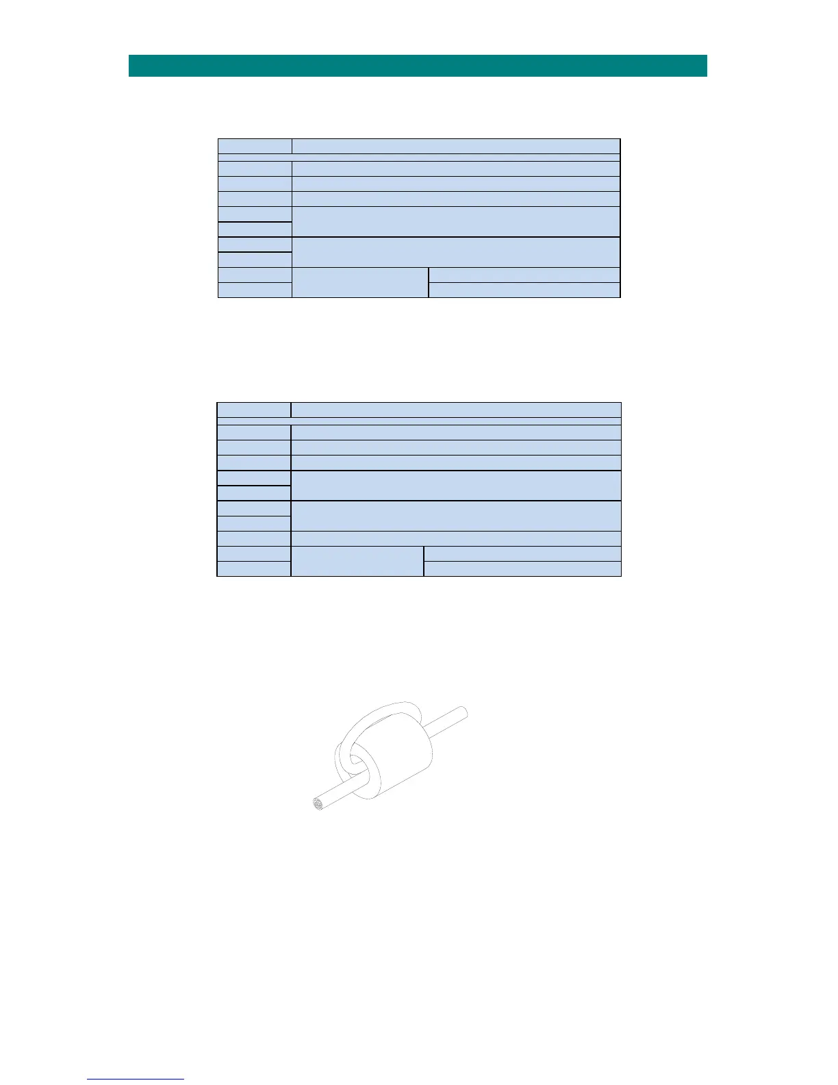
FERRITE CORE
Thenetworkwiringshouldbeloopedthroughaferritecorebeforebeingconnectedtotheterminationboard.Thiswill
suppressanyvoltagetransientsinducedonthenetworkwiringandgreatlyreducethelikelihoodofdamagetothemain
CPUboard.
NETWORKCABLE
LOOPNETWORKCABLETHROUGHTHE
FERRITECOREBEFORECONNECTING
TOTHEADVENTxtTERMINATIONBOARD
TOTERMINATIONBOARD
Fourferritecoresareprovidedinthekitofparts withtheAdventxtcontroller‐foradditionalferritecoresorderTynetec
P/No.T06050.