DocNo.FM0410issueM‐1Page22
REMOVE BOARD TO
TERMINATE THEN
REFIT AS SHOWN
16
17
18
19
20
15
14
13
12
11
98765
4
3
21
FIT 4K7 RESISTOR ACROSS
TERMINALS 2 & 9
SET
BI NARY
ADDRESS
1 2345678
ON
12345678
ON
LK2
LK3
LK1
ALL "OFF"
A00518
A00399
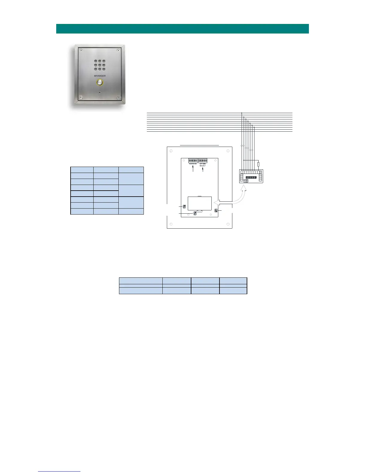
ZXT250/255 MANAGER CALLPOINT
FIT LK3 IN
POSITION "A"
POSITION "A"
FIT LK2 IN
FIT LK1 IN
POSITION "B"
24V
12V
0V
TX+
TX-
SP1
SP2
MI C
PA1
PA2
24V
12V
0V
TX+
TX-
SP1
SP2
MIC
PA1
PA2
15.MANAGERCALLPOINTINSTALLATION
TheManagerCallpoint(P/No.ZXT250)isanexternal
speechunitusedtoinitiateacallfromoutsidethebuilding.
Itisconnectedtothesystemnetworksimilartoastandardintercom.
INSTALLATION
Thestandardbackboxisdesignedforflushmounting‐asurfacemountbackbox(P/No.HM0821)orastainless surface
cowling(P/No.HM1125)isavailableseparately.Donotcutaholeinthetopfaceofthebackboxforcableentryas thismay
allowwatertoenteranddamagetheelectroniccomponents.Thecut‐outdimensionsgivenbelowwillallowthebackbox
tofitflushintothewallordoorscreenwiththebezeloverlappingbyapprox.14mmonallsides.
PartNo. Height Width Depth
ZXT250 210mm 170mm 60mm
Thebackboxshouldbesealedwithsuitablemastictopreventwateringress.Allbackboxesmustbeearthbondedinline
withcurrentIEEregulations.Thefasciaisfixedby4offM5x12mmAllenkeyscrewswhichrequirea3mmAllenkeytool.
TERMINATION
CarefullyunplugtheterminationboardoffthebackoftheManagerCallpointtogainaccesstothescrewterminals.
Connecttothesystemnetworkwiringasshownabove,fita4K7resistoracrossterminals2&9topreventan“opencircuit
fault”beingreported,andthenrefittheterminationboard
ensuringcorrectorientation.Note;thereisnoPAfacilityona
ManagerCallpoint.
DIL SWITCHES & LINKS
The“OPTIONSELECT”DILswitchshouldbesetallOFFandthe“ADDRESS” DILswitchshouldbesetwiththenextavailable
unique8bitbinaryaddress.FitLinksLK1inposition“B”&LK2/LK3inposition“A”.
DOOR LOCK CONNECTION
TheN/Ocleancontactoutputonterminals16&17canbeusedtorelease an electriclock.Powerforthelockreleasemust
betakenfromanadditionalPSU‐nottheAdventxtnetwork.Alternatively,anauxiliaryrelayoutputontheAdventxt
controllercanbeprogrammedtoactivatewithanyDTMF
character‐seetheAdventxtProgrammingManual(TynetecDoc
No.FM0411).
ADVENT xt
NETWORK
Terminal Network Cable
1 24VDC
Pair1
2 0V
3 TX+
Pair2
4 TX‐
5 SP1
Pair3
6 SP2
7 MIC