DocNo.FM0410issueM‐1Page15
A00399
ENTRY
CABLE
A
A
A
A
B
B
C
C
CABLE ENTRY
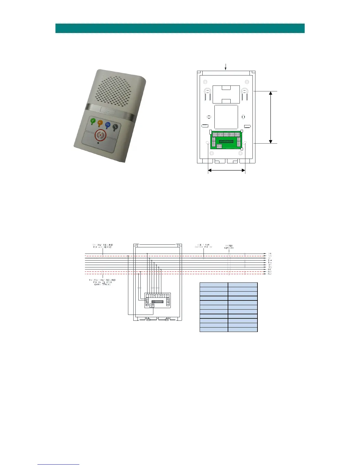
9.INTERCOMUNITINSTALLATION
Theintercomunitshouldbewallmountedinacentrallocationwithineachdwelling.Screwfixtheintercomrearsecurely
tothewallusingthe4holesmarked“A”.The2holesmarked“B”canbeusedforanembeddedbox.Ensurethecaseisnot
twistedasthismay
preventthelidfittingcorrectly.
97mm
70mm
Thenetworkcableshouldloop‐inandoutofeachintercomviathecableentrychannelonthetoporthesquarecut‐outin
therear.Whereverpossibleavoidcableentryfrombelowasthismayinterferewiththeoperationoftheemergency
pullcord.Thecableclipsmarked“C”canbeusedtoretainspare coresandpreventpossibleshortcircuitswhenthe
intercomfrontisfitted.
INTERCOM TERMINATION
Thenetworkwiringisterminatedontheinterconnectboardintherearsectionoftheintercomasshownbelow;
NETWORKNETWORK
WIRING
WIRING
INOUT
The12Vconnection(COM)isonlynecessaryifthereareauxiliarydeviceswithinthedwellingthatrequirea12VDCsupply.
Likewise,thePA1/PA2connectionisonlynecessaryforthepublicaddressoptionorifdoorentrytelephonesarefitted.
Ifallcoresareavailableinthenetworkcableitisgoodpracticetomakealltheconnectionsforpossible futureupgrades.
Intercom Network
1 24VDC
2 0V
3 TX+
4 TX‐
5 SP1
6 SP2
7 MIC
11 PA1
12 PA2
COM 12VDC
FIXINGHOLES
“B”ON60mm
CENTRES