23.COMBINEDINTERCOMINSTALLATION
Combinedintercomsprovidebothwardencallanddoorentry
functionsinasingleunit.TheyareavailablewithPA,Extracare
andanintegral433MHzReceiverforusewithanoptional
RemoteControl.
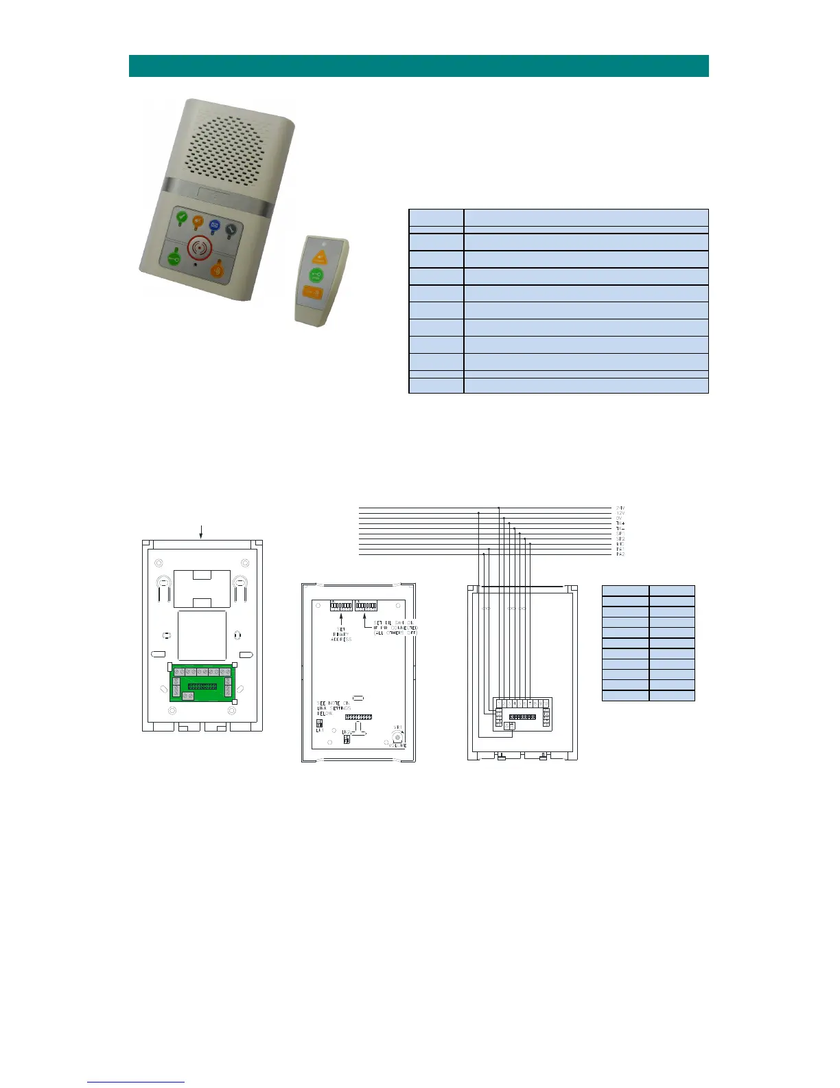
TheRemoteControlcanbeusedtoanswerdoorentrycallsand
releasethedoorlock.Itcanalsobeusedtoselectprivacy
mode,acknowledgeI’mOKandplayamessagewaiting.
INSTALLATION
TheAdventxtcombinedintercomunitshouldbewallmountedintheroommostoftenusedbytheresident.Screwfixthe
intercomrearsecurelytothewallusingthe4holesmarked“A”‐the2holesmarked“B”canbeusedforanembedded
box.Ensurethecaseisnottwistedasthismaypreventthelidfittingcorrectly.
SYSTEM
NETWORK
TERMINATION
Thenetworkcableshouldloop‐inandoutofeachcombinedintercomviathecableentrychannelonthetoporthesquare
cut‐outintherear.Whereverpossibleavoidcableentryfrombelowasthismayinterferewiththeoperationofthe
emergencypullcord.Thecableclipsmarked“C”
canbeusedtoretainsparecoresandpreventpossibleshortcircuitswhen
theintercomfrontisfitted.
ThenetworkwiringisterminatedontheinterconnectboardintherearsectionoftheAdventxtintercomasshownabove.
Ceilingpullcords,smokedetector,PIRandauxiliaryinputdevicesareconnectedthesameasastandardintercom,see
section10ofthismanualortheAdventxtwiringdiagramDrgNo.ZXT100sheet5.
Beforefittingtheintercomfrontthe“Address”and“OptionsSelect”DILswitchesmustbeset.ThejumperlinksLK1&LK2
mustalsobesetinthecorrectposition.
PartNo. Description
ZXT280 CombinedIntercom
ZXT281 CombinedIntercom+RX
ZXT282 CombinedIntercom+PA
ZXT283 CombinedIntercom+PA&RX
ZXT284 CombinedExtracareIntercom
ZXT285 CombinedExtracareIntercom+RX
ZXT286 CombinedExtracareIntercom+PA
ZXT287 CombinedExtracareIntercom+PA&RX
ZXT235 OptionalRemoteControl
Auxiliaryinputdevices
suchceilingpullcordsand
smokedetectorsare
connectedthesameasa
standardintercom.
OPTIONAL
REMOTECONTROL
Intercom Network
1 24VDC
2 0V
3 TX+
4 TX‐
5 SP1
6 SP2
7 MIC
11 PA1
12 PA2
COM 12VDC