71
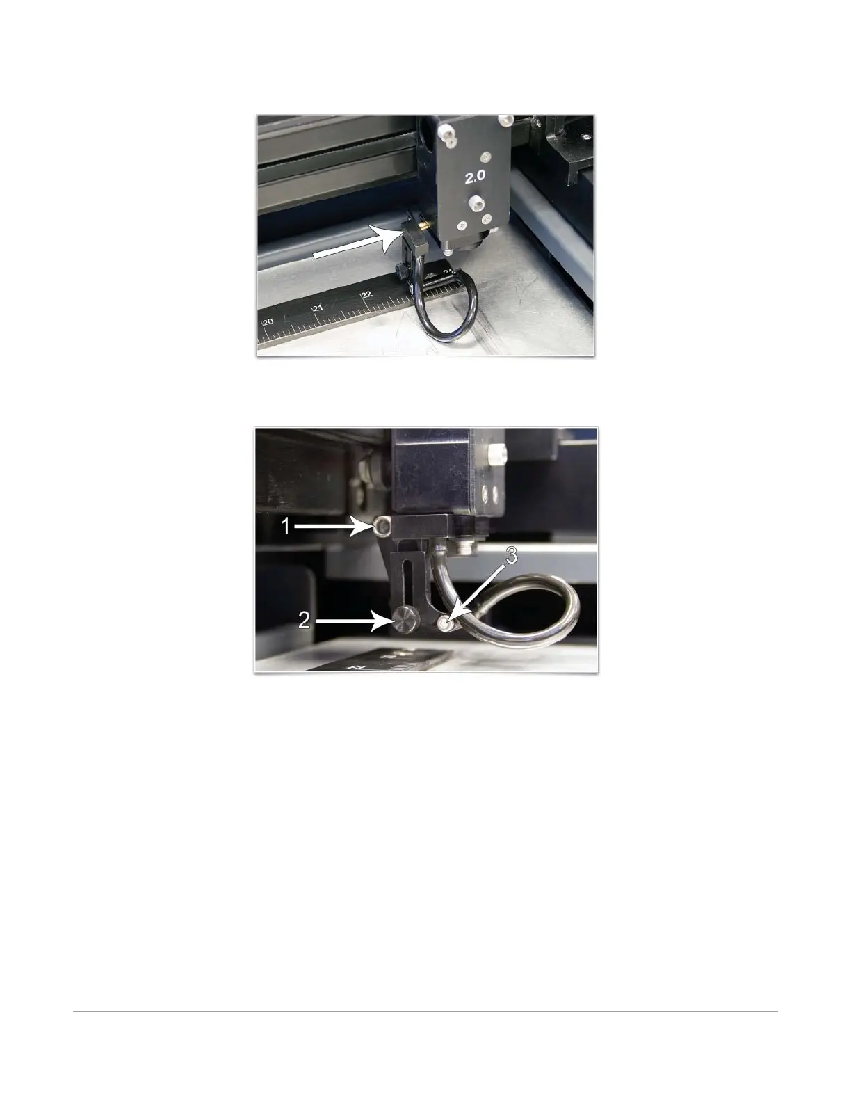
2. Insert the Lateral Gas Assist Attachment’s brass tube into the forward of the two holes on the carriage.
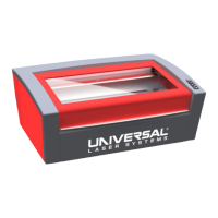
3. Use the thumbscrew (1) removed earlier to hold the Lateral Gas Assist Attachment in place. Adjust the
Lateral Gas Assist Attachment’s height by loosening the thumbscrew (2) and adjusting it up or down.
Tighten the thumbscrew once it is at the desired height. To adjust the angle of the gas flow, turn the
screw (3) in small increments to direct the gas jet to the desired position over the material. A convenient
way to align the gas flow is to focus on the material to be processed and then align the nozzle using the
angle and height adjustments toward the red target laser which is on when the laser system is powered
on and the top door is open.
Note: If you remove the Lateral Gas Assist Attachment, always remember to reattach the mounting
thumbscrew (1) to seal the gas feed port.
Coaxial Gas Assist Attachment (Cone)
To install the Coaxial Gas Assist Attachment, insert the Coaxial Gas Assist Attachment (1) into the Coaxial Gas
Assist Attachment base completely until it bottoms out. Tighten the screw on the side of the Coaxial Gas Assist
Attachment base (2) until it is snug. To remove the Coaxial Gas Assist Attachment, simply loosen the screw (2)
and pull the Coaxial Gas Assist Attachment straight down. Do not remove or loosen the Coaxial Gas Assist
Attachment base mounting screws (3) & (4) to mount or dismount the Coaxial Gas Assist Attachment. These