78
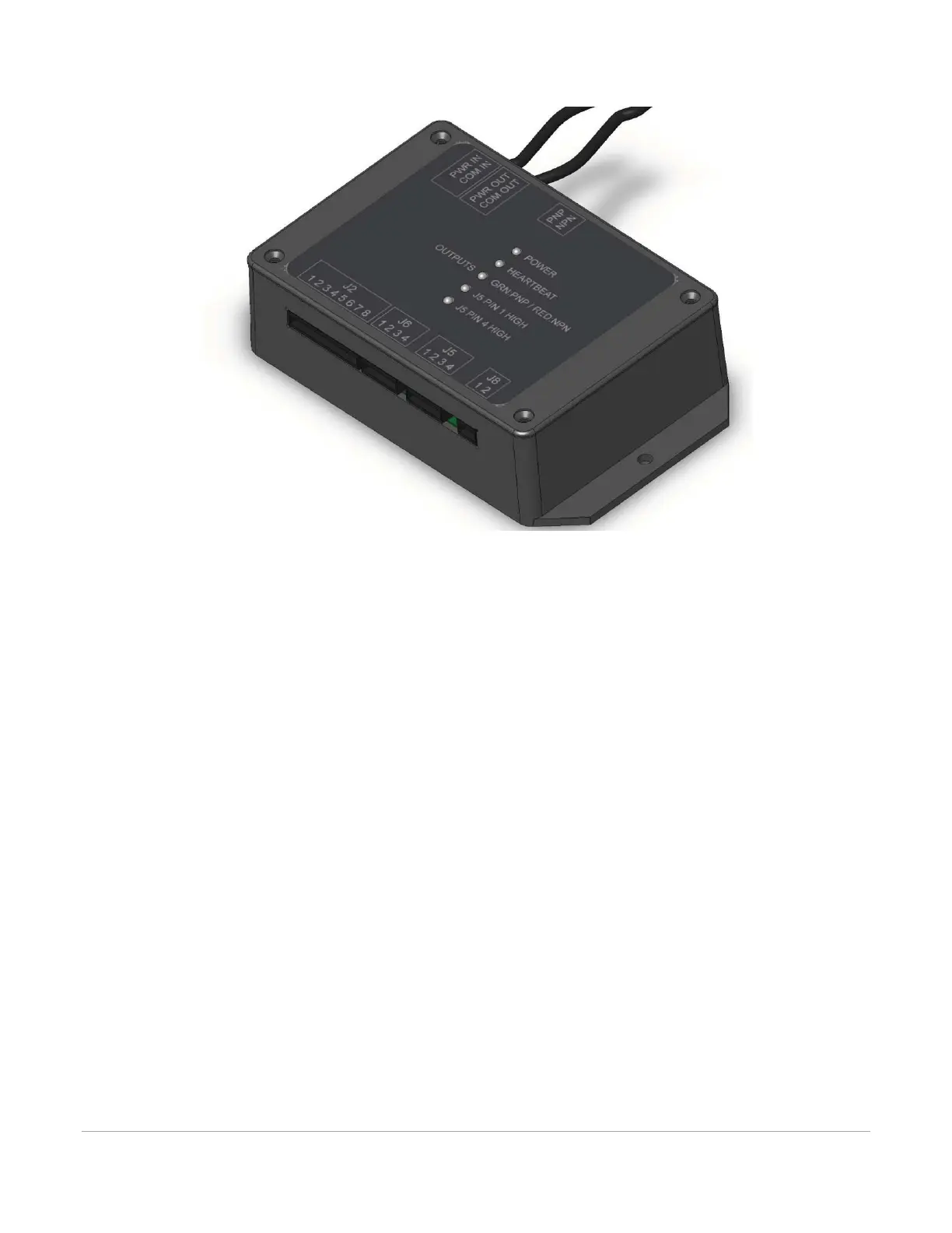
3. Then connect the other end of the patch cable to the PWR/COM IN RJ9 connector at top of
Automation Interface.
External Wiring
The Automation Interface connector J2 is used to wire external signals to six programmable inputs which
can initiate various laser functions. To trigger a function, supply between 5V DC to 24V DC to one of the
input pins as shown below. It is not necessary to limit current with a resistor to the input pins. The pulse on
the input pins should be held high longer than 5mS in order to register.