75
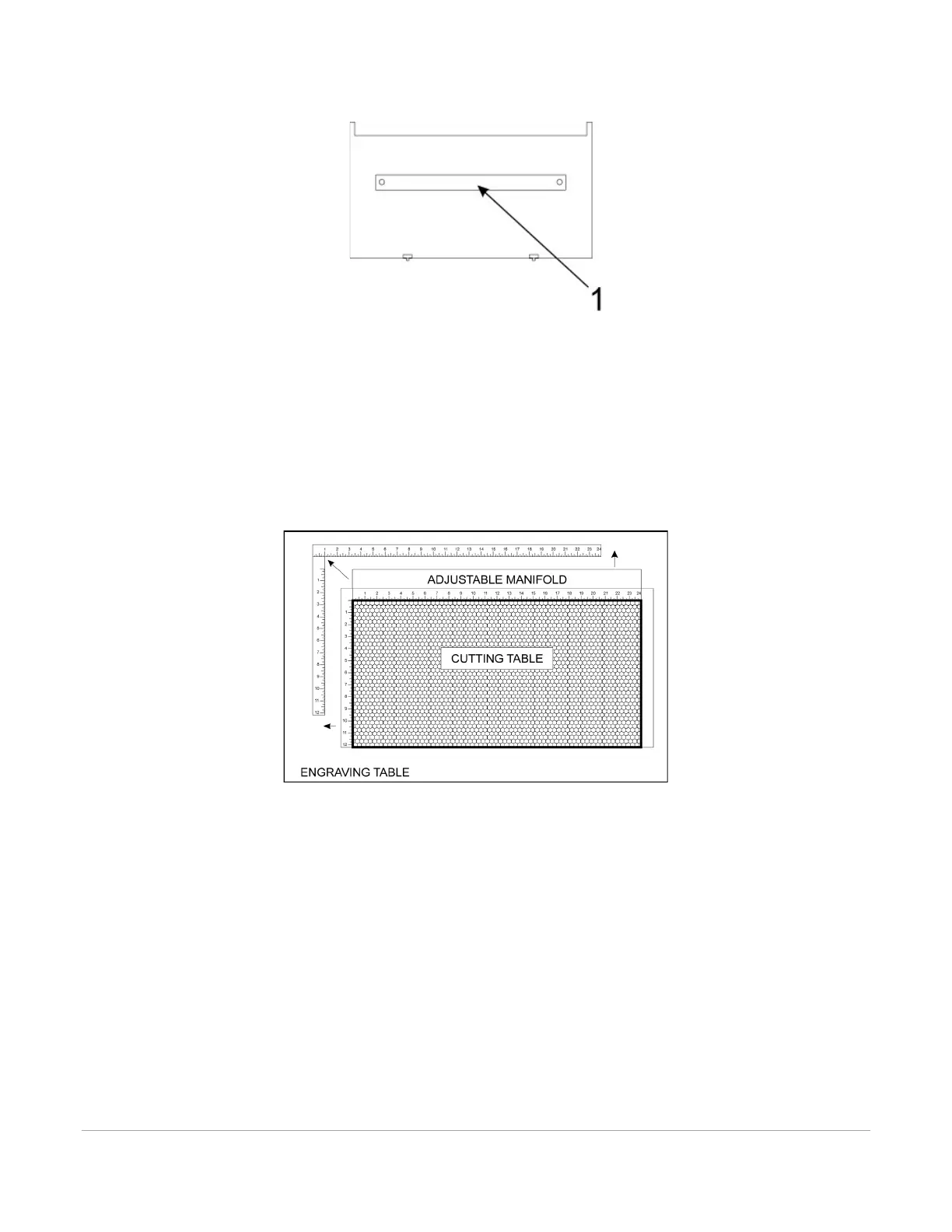
3. Remove the strip(s) from the exhaust plenum(s) (1) with a screwdriver.
4. Before installing the cutting table in the laser system, loosen the duct adjusting thumb screws on the
side of the cutting table just enough to allow the manifold to slide in and out. Extend the adjustable
manifold out as far as it can go.
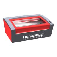
5. Open the front door of the laser system and carefully insert the cutting table into the laser system,
so that the four feet on the bottom of the cutting table are resting on the engraving table in the
laser system. Then slide the table back and to the left until the two rear feet are up against the X-
axis ruler and the left rear foot is up against the Y-axis ruler. The feet of the cutting table must be
aligned properly with the X and Y rulers in the laser system in order to ensure that the rulers on the
cutting table line up with the processing field.
6. Make sure the adjustable manifold is squarely up against the exhaust plenum in the back of the
machine to ensure good exhaust flow below the material and tighten the four screws on the side of
the cutting table. Be careful not to move the cutting table while tightening the screws.
7. You can use the red pointer diode to ensure the cutting table is aligned to the processing field, by
moving the red pointer around the edge of the field using the manual motion keys. If the cutting
table is not aligned, check that the feet are properly pressed against the X Y rulers in the machine. If
the feet are properly positioned and the rulers are still not aligned, you can adjust them by
loosening their mounting screws slightly (you may have to remove the cutting table to do this).
Adjust the rulers and then retighten the screws.