Configuration and Programming
P/N 06-237041-001 3-41 February 2011
Note: Each simulated alarm report must be manually de-activated via this menu operation
before the system can be returned to normal operating condition.
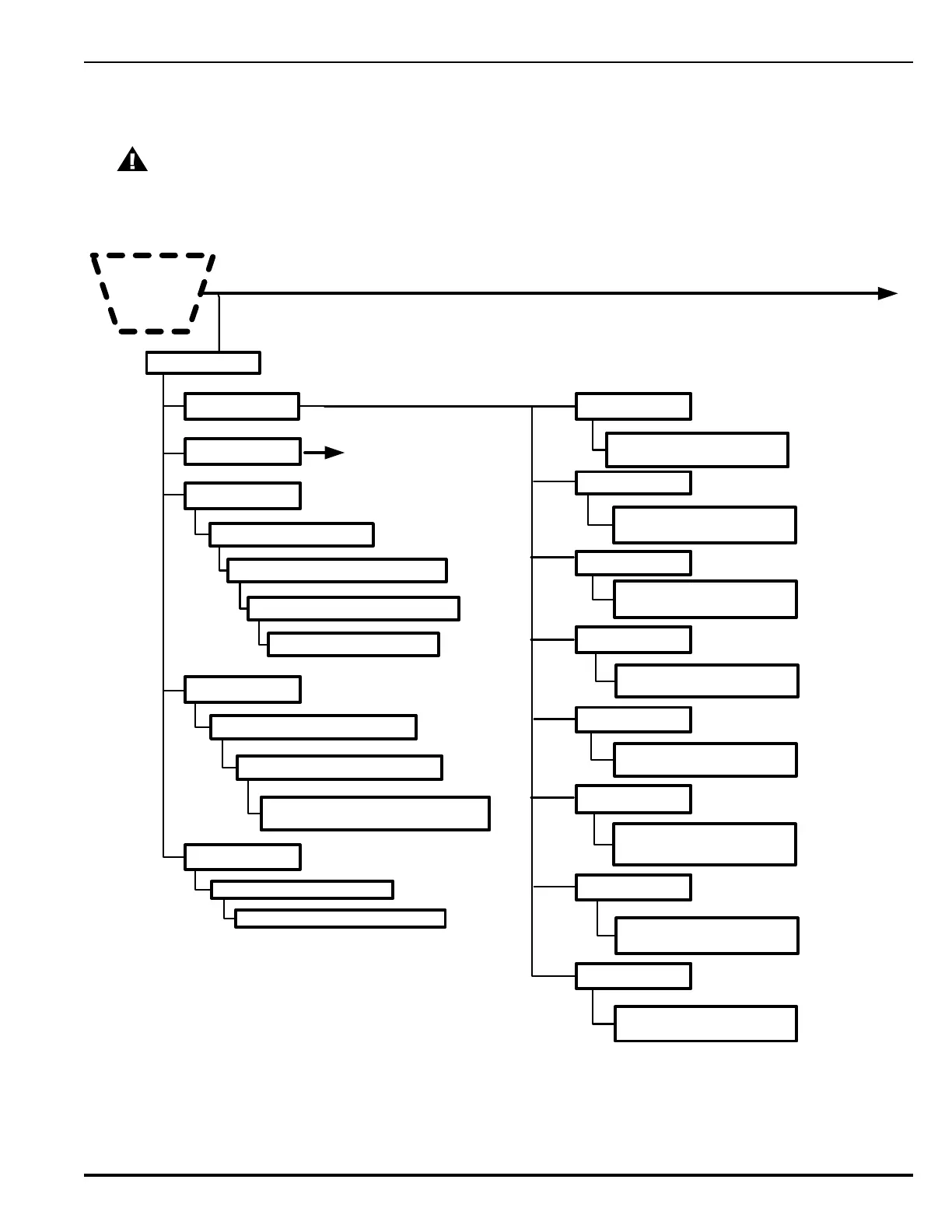
Figure 3-33. FenwalNET 8000-ML Test Menu Functions (Cont’d - Fig. 3 of 5)
CAUTION
Isolate all releasing outputs using the Isolate function and physically disconnect the wiring to
all agent-release and pre-action-sprinkler circuits and auxiliary control circuits before running
any alarm-simulation test(s). Restore the system to normal operating condition at the
conclusion of all simulated alarm tests and any other functional tests that were performed.
4. TEST
Cont’d
*
SG1
1. Activate 2. De-activate
6. Outputs Test
1: NAC 1 *
2: NAC 1 *
3: RNAC 1 *
4: RNAC 2 *
5: Relay 1 *
6: Relay 2 *
7: Relay 3*
SG3
1. Activate 2. De-activate
RLY2
1. Activate 2. De-activate
RLY1
1. Activate 2. De-activate
SG2
1. Activate 2. De-activate
SG4
1. Activate 2. De-activate
RLY3
1. Activate 2. De-activate
1. On Board Circuit
3. Annunciator
2. Backplane Circuit
See next Figure.
5. RRM Group *
1. Activate 2. Deactivate
Enter RRM Group Number * (1-7)
4. SLC Outputs*
1. Activate 2. Deactivate ___
SLC Outputs Test
SLC Devices From *__ to ___
(1-255)
Enter LAM Address (1-16)
Enter Output Range (01-16): __ to __
1: Activate 2: De-Activate 3: Pulse
1: Default 2: Yellow 3: Red
8: Trouble Relay*
RLY4 Trouble Relay
1. Activate 2. De-activate
*=
Level-2 (Installer) Password required .
Enter SLC Module Number (1-8)
6
 Loading...