Configuration and Programming
P/N 06-237041-001 3-43 February 2011
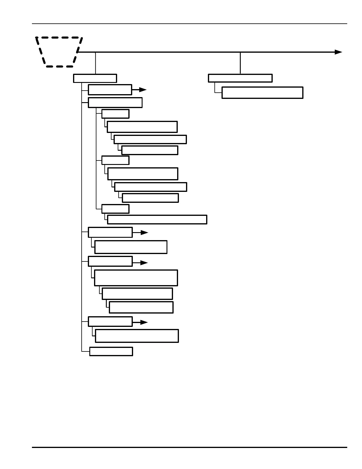
Figure 3-34. FenwalNET 8000-ML Test Menu Functions (Cont’d - Fig. 4 of 5)
FOOTNOTES (Figure 3-34):
7 On Board Circuit. Activate or De-Activate Control Modules (i.e., as AO, ASM or RRM).
Purpose: To manually activate or de-activate one or more control modules during system testing to
confirm the proper operation of control functions via AOs, NAC operation via ASMs or RRMs.
4. TEST
Cont’d
*
6. Output Tests
*=
Level-2 (Installer) Password required .
2. BACKPLANE CIRCUIT
1. RNAC
Backplane Test
1. Activate 2. Deactivate
Enter Module Logical Address __
Enter Circuit Number__
1: On Board Circuit
2. Relay
Backplane Test
1. Activate 2. Deactivate
Enter Module Logical Address __
Enter Circuit Number__
3. City Tie
1. Activate 2. Deactivate 3. Report TBL
See previous Figure.
7
SLC Module Selection
Enter SLC Module Number (1-8):__
3. Annunciator
See previous Figure.
Output Activation Mode
Enter the LAM Number (01-16):_
4. SLC Outputs*
See previous Figure.
SLC Output Device
1: Activate 2: De-activate
SLC Output Devices
SLC Devices From ___ to ___
5: RRM Group *
See previous Figure.
8
RRM Group Devices
1: Activate 2: De-activate
6. Output Group
Ground Fault Detection
No Ground Fault Present on System
7. Find Ground Fault
*
 Loading...