Routings for Power-Limited and Non-Power-Limited Wiring
February 2011 E-6 P/N 06-237041-001
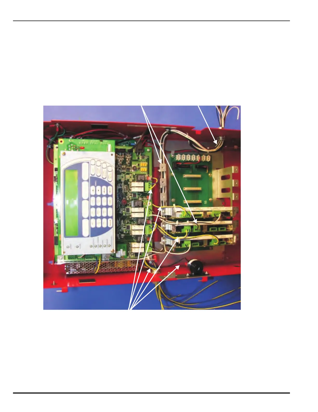
Figure E-5. An Example of a Typical FenwalNET 8000-ML Wiring Scenario
Note: Figure E-5 illustrates a typical wiring scenario where 3 expansion cards are included in the system with power-limited
wiring (Black/White wires) and non-power-limited wiring (Blue/Yellow wires) properly spaced. Using standard wiring tools
(such as P-clamps and tie-wraps), in conjunction with the enclosure standoffs, brackets and card cage frame, power-limited
and non-power-limited types of circuits can easily be connected and harnessed to meet the 1/4-inch separation requirement.
Power-limited wiring is
routed through knockout
on right side of enclosure.
Power-limited wiring is
shown harnessed and
bundled along the top
of the card cage frame
with 1/4-inch (min.)
separation distance
from non-power-limited
wiring.
Non-power-limited wiring
Non-power-limited wiring
is routed through knockout
on left side of enclosure.
 Loading...