Conversion Instructions for FenwalNET 2000
February 2011 H-4 P/N 06-237041-001
5. After marking the hole location, remove dry-fitted parts and drill a 0.189 hole for #8 machine
screw/nut (surface mounted enclosure) or a 0.136 hole for self-threading screw (recess mounted
enclosure). Deburr the hole and clean all debris from the empty cabinet. Vacuum all metal
filings.
6. Insert a #8 screw/nut or self-threading screw into the hole just drilled. Tighten to secure the
bracket.
7. Replace the #8 nut on the Earth Ground lug at the top left of the enclosure.
8. Remove tape from wires which were previously taped.
9. On the top tier, install the Power Supply and PMU Board according to the installation
instructions provided in Chapter 2 of this manual (or packaged individually with the equipment).
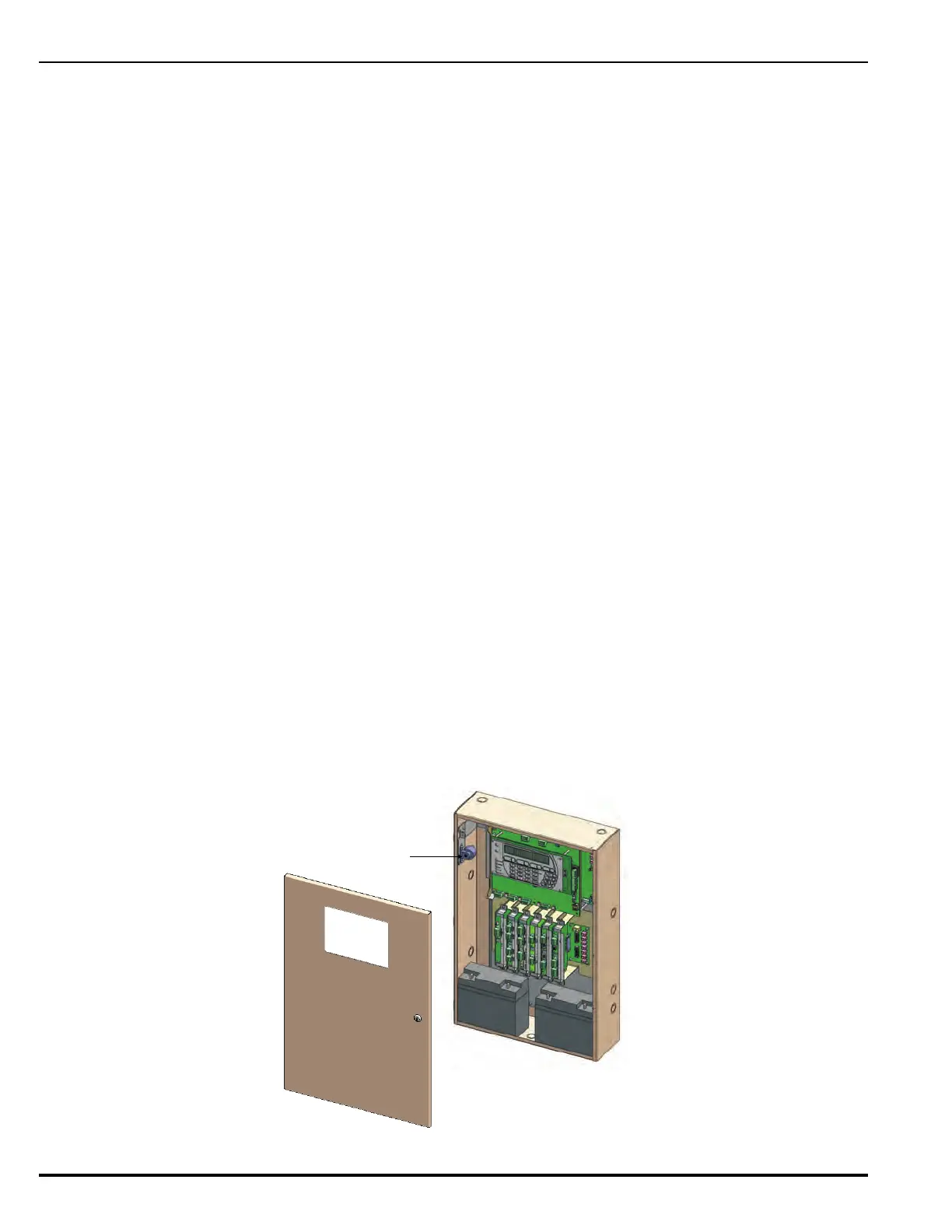
10. With the PMU Board installed, unscrew the nut which is in place on the stud located on the left
side of the enclosure. Refer to the illustration below for location of the stud.
11. Place the Audible PMU Trouble Sounder bracket assembly over the stud (oriented as shown in
Figure H-2).
12. Replace the nut and tighten to secure bracket assembly in place.
13. Next, connect wires from the Audible PMU Trouble Sounder to the PMU Board.
• Connect the positive (red) wire from the sounder to the Trouble Relay Normally Open
terminal (labeled “TBL RELAY NO”).
• Connect the negative (black )wire from the sounder to the available negative Battery terminal
(labeled “Battery —”).
• Connect the power jumper (red) wire between the available positive Battery terminal (labeled
“Battery +”) and the Trouble Relay Common terminal (labeled “TBL RELAY C”).
14. Lay all wires flat against the back of the enclosure. Maintain 1/4-in. separation between power-
limited and non-power-limited wiring.
Note: A suggested method is to route the wires from the Audible PMU Trouble Sounder over the
small bracket attached to the enclosure.
15. .Continue the installation procedure by installing the Main Controller Board and Keypad/Display
according to the installation instructions provided in Chapter 2 of this manual (or packaged
individually with the equipment).
16. On the bottom tier, install any optional equipment according to the installation instructions
provided in Chapter 2 of this manual (or packaged individually with the equipment).
17. After all electronics have been installed, place the replacement door on the enclosure hinges.
Figure H-2. The Retrofitted Enclosure with FenwalNET 8000-ML Electronics Installed
PMU Audible
Trouble Sounder
 Loading...