Installation
February 2011 2-34 P/N 06-237041-001
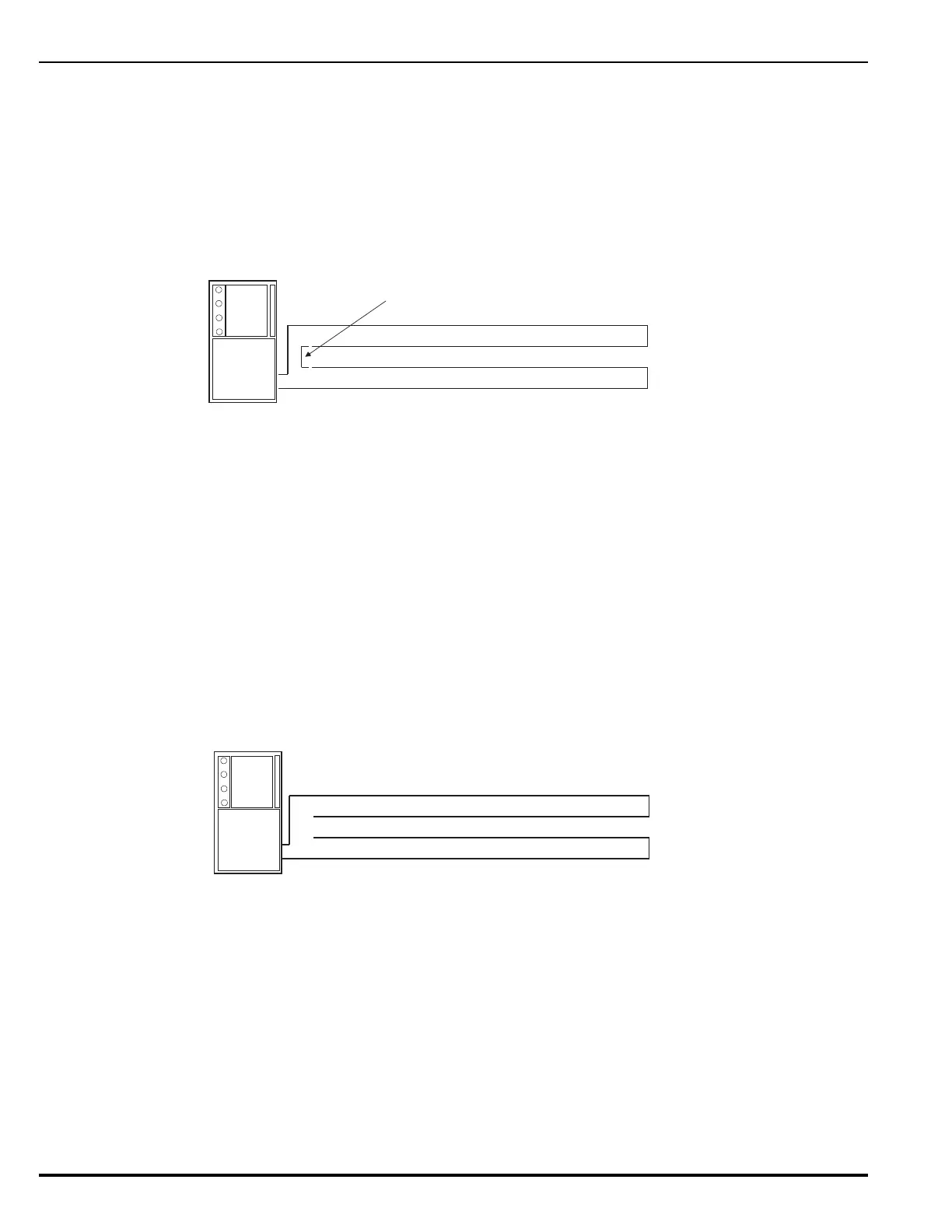
2-8.5.5 MEASURING CLASS-A SLC WIRING RESISTANCE
Note: The following resistance reading MUST be taken PRIOR to the installation of any loop device.
The total wiring resistance from the start of the “Out” leg to the end of the “Return” leg cannot exceed
40 ohms. Use the following procedure to determine the wiring resistance.
1. Short the “Out” and “Return” legs as shown in Figure 2-28. Measure the resistance using the
other two terminating points at the control unit
2. Remove the shorting jumper after the resistance measurement.
Figure 2-28. Measuring CLASS-A SLC Wiring Resistance
2-8.5.6 MEASURING CLASS-A SLC WIRING CAPACITANCE
The total wiring capacitance cannot exceed 0.5 F. Use the following procedure to determine the
wiring capacitance.
Note: The following capacitance reading MUST be taken PRIOR to the installation of any loop
device.
1. Measure the capacitance using the wiring that will connect to control unit terminals J19-1 and
J19-3 (Terminals J19-2 and J19-4 MUST remain disconnected from the control unit) as shown
in Figure 2-29.
Figure 2-29. Measuring CLASS-A SLC Wiring Capacitance
2-8.5.7 MEASURING CLASS-A, STYLE 7 SLC WIRING RESISTANCE AND CAPACITANCE
Contact your authorized Fenwal distributor for the best method of ensuring proper total resistance
and capacitance for CLASS-A, Style 7 SLC loop wiring.
Jumper
Out Leg
Return Leg
Volt-Ohm Meter
Out Leg
Return Leg
Capacitance Meter
 Loading...