channel.
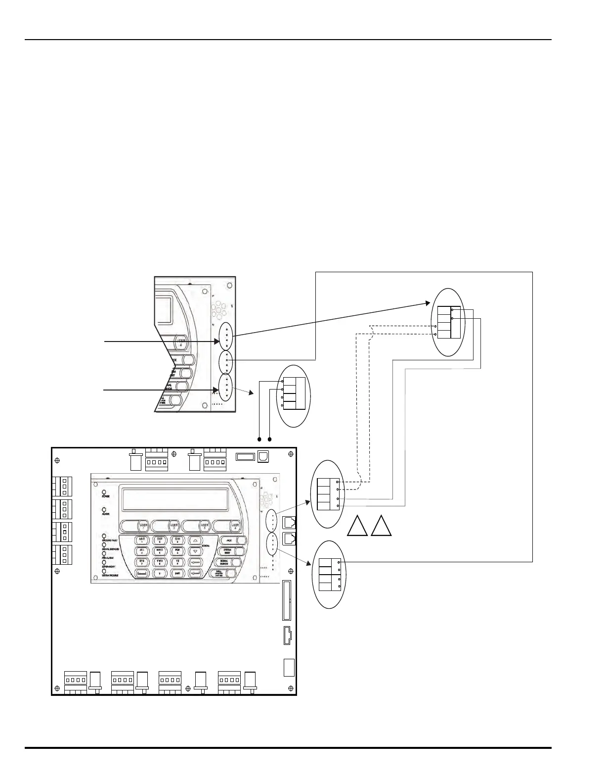
Figure 2-41. RS485 Wiring Diagram for Remote Devices to MCB
TB1
RELAY 1
NO C
NC
TB2
RELAY 2
NO C
NC
TB3
RELAY 3
NO C
NC
TB3
TBL RELAY
NO
C
NC
J20 J19
SLC 2
IN+
OUT-
IN-
OUT+
USB HOST USB DEVICE
J17
R-NAC 1
IN+
OUT-
IN-
OUT+
NORMISOL
R-NAC 2
IN+
OUT-
IN-
OUT+
J18
NAC 1
IN+ IN-
OUT+ OUT-
J16
ISOL NORM
ISOLNORM ISOLNORM
ISOL NORM
NAC 2
IN+ IN-
OUT+ OUT-
J15
ISOL NORM
RS232 A
RS232 B
J10
24 VDC IN
J2
PMU COMMS
OUT
J9
BACKPLANE
COMMS OUT
RS485
IN-B
IN-A
OUT-A
OUT-B
Main Controller Board
(MCB)
SLC 1
IN+
OUT-
IN-
OUT+
RS485
IN-B
IN-A
OUT-A
OUT-B
S P
24 VDC PWR
IN-
IN+
OUT+
OUT-
Communications Circuit
(J8)
Voltage: 24 VDC
Current: Per RS485 Standard
Recommended Wire: Twisted, shielded,
low-capacitance, fire-alarm wire
Max. Wire Length: 4,000 Ft. per twisted pair
Use the following remote control modules only
:
Module Type Model No.
Display / Control RDCM
Display R-LAM
J8
J8
J4
J8
J
8
J4
RDCM
Installation Notes:
RS485 circuits must be terminated at the
first and last device in the circuit. Set termination
resistor SW2 (located on the back of the Keypad/Display
and RDCM boards) to the ON (terminated) position
by moving the tiny white lever.
For remote synchronization between RDCMs, R-LAMs and the
control unit (having power supply connections common to all),
install wire from LED SYNCH OUT+ of the originating device to
LED SYNCH OUT- of the first remote peripheral device. Continue
for as many remote devices in the system.
Note: An R-LAM cannot be an originating device.
For Dual Channel Installation
On the R-LAM, the location of these
2 connectors is reversed; i.e., its J6
(PWR IN) 24 Vdc connector is at
the top, and its J8 (RS485) bus
connector is at the bottom.
J6
1.
2.
+
-
J6
OUT+
OUT-
LED SYNCH
PSU TBL
J6
 Loading...