EasyManuals Logo

Vacon 100X series User Manual

Vacon 100X series
172 pages
To Next Page IconTo Next Page
To Previous Page IconTo Previous Page
Page #151 background imageLoading...
Page #151 background image
Parameters vacon • 148
Service support: find your nearest Vacon service center at www.vacon.com
6
P3.13.7.1 ENABLE SP 1
P3.13.7.2 S
ETPOINT 1 MAX COMPENSATION
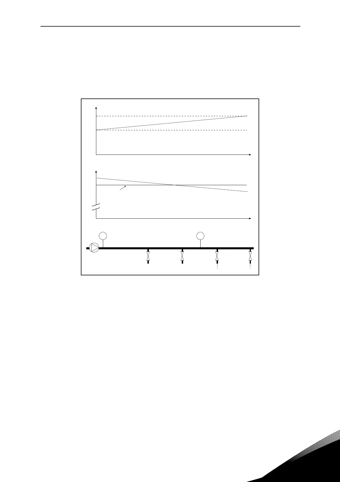
The sensor is placed in Position 1. The pressure in the pipe will remain constant when we have
no flow. However, with flow, the pressure will drop farther down in the pipe. This can be com-
pensated by raising the setpoint as the flow increases. In this case, the flow is estimated by the
output frequency and the setpoint is linearly increased with the flow as in the figure below.
Figure 55. Enable setpoint 1 for pressure loss compensation
P
T
P
T
9102.emf
Position 1 Position 2
Pressure
No flow
Wi
t
h
f
l
o
w
a
n
d
c
o
m
p
e
n
s
a
t
i
o
n
Pipe length
Setpoint
Max Freq and FlowMin Freq and Flow
Setpoint + Max compensation
Setpoint

Table of Contents

Questions and Answers:

Question and Answer IconNeed help?

Do you have a question about the Vacon 100X series and is the answer not in the manual?

Vacon 100X series Specifications

General IconGeneral
Product seriesVacon 100X
CategoryController
Protection ClassIP66 / Type 4X
Frequency50/60 Hz
Braking ChopperBuilt-in
Ambient Temperature-10°C to +40°C, up to +50°C with derating
Control MethodVector control
Input Voltage525-690V
Communication OptionsCANOpen
MountingWall-mounted
EMC FilterBuilt-in
Cooling MethodAir-cooled
Protection FeaturesOvertemperature, Overvoltage, Undervoltage

Related product manuals