Non-regenerative front end vacon • 193
Local contacts: http://drives.danfoss.com/danfoss-drives/local-contacts/
11
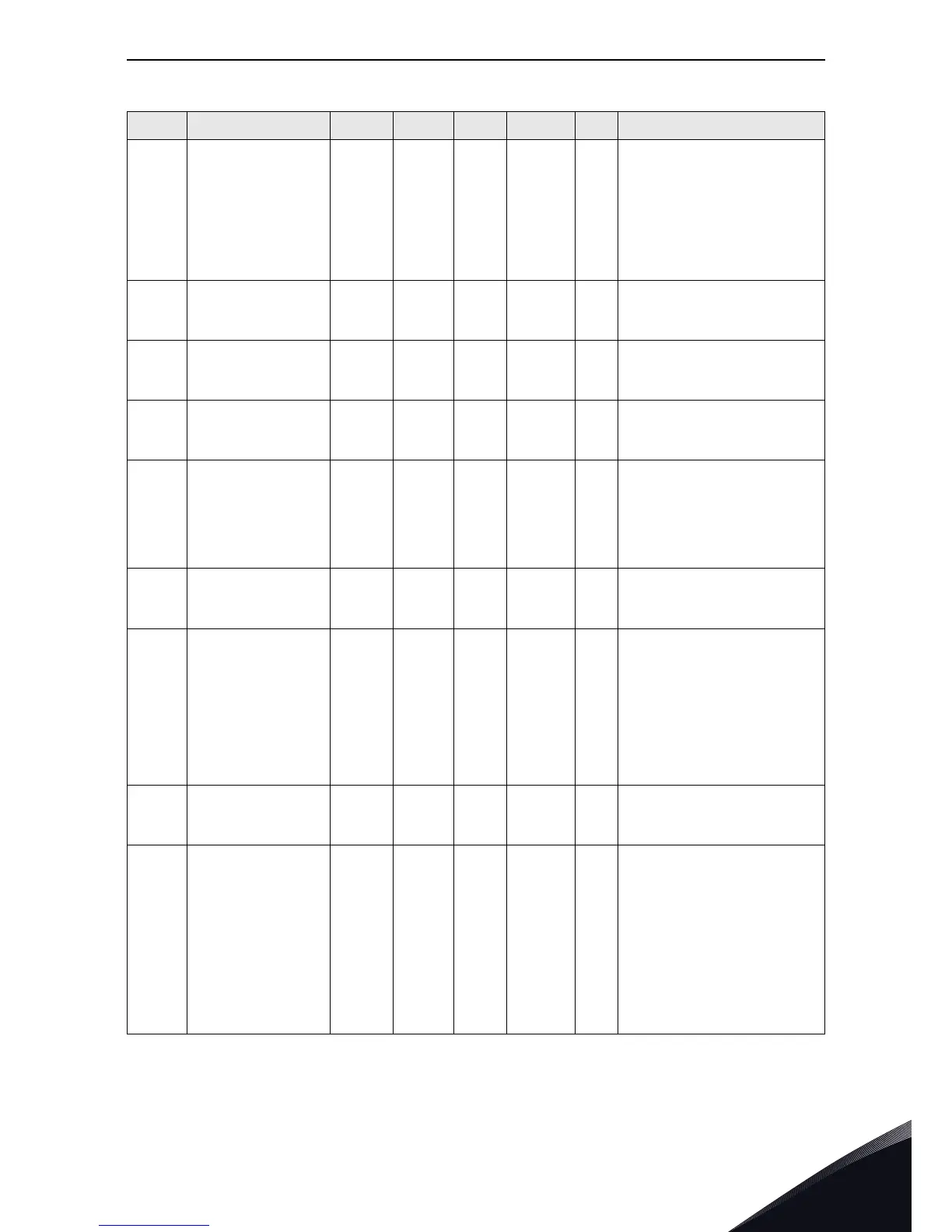
P2.4.7 ChokeTempFauMode 0 3 1 1951
Response to Choke Temp mode
when Temp measurement is
using digital input (DI)signals or
PT100 signal
0=No action (DI)
1=Warn + Fault (after delay) (DI)
2=Fault (DI)
3=PT100
P2.4.8 ChokeOTFaultDela 0 30 min 5 1952
When choke temp fault mode=1,
after this time, warning will be
changed to fault
P2.4.9 ChokeOTWarnLevel -30.0 200.0 deg 110.0 1953
Choke temp using pt100. If temp
is over this limit, a warning will
generate
P2.4.10 ChokeOTFaultLeve -30.0 200.0 deg 130.0 1954
Choke temp using pt100. If temp
is over this limit, a fault will
generate
P2.4.11 Ext Fault Mode 0 4 0 1955
External fault mode selection
0=No action
1=Warnng + Fault(after delay)
2=Fault
3=Inv Warning+ Fault(after delay)
4=Inv Fault
P2.4.12 Ext Fault Delay 0 600 min 0 1956
The Delay Time for triggering an
external fault after an external
warning is active.
P2.4.13 CoolingFaultMode 0 4 0 1957
Fault mode selection for liquid
cooling fault from digital input
signal
0= No action
1= Warning + Fault(after delayed)
2= Fault
3= Inv Warning + Fault (after
delay)
4= Inv Fault
P2.4.14 CoolingFaultDela 0 3600 s 1 1958
A delay time for triggering a
liquid fault after liquid warning is
active
P2.4.15 E Stop Mode 0 4 0 1959
E stop mode selection
0=No action
1=Warning, ditial input goes to
TRUE
2=Fault, digital input goes to
TRUE
3=Inv Warning, digital input goes
to
FALSE
4=Inv Fault, digital input goes to
FALSE
Table 89. Protection G2.4
Code Parameter Min Max Unit Default ID Desciption