100
Model Code Page
22. Fuel system
15. 5. 1996
8050--8550 220 12
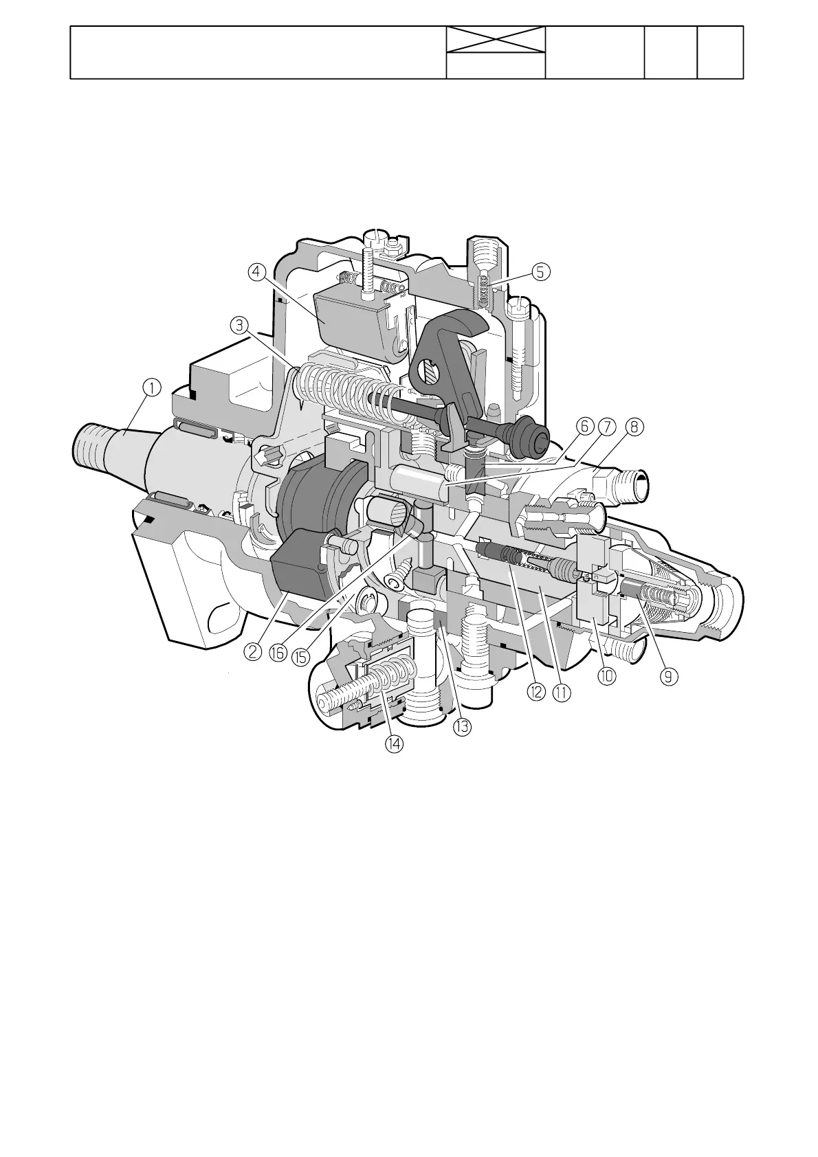
Stanadyne distributor pump
1. Drive shaft
2. Governor weights
3. Governor spring
4. Stop solenoid
5. Overflow valve
6. Metering valve
7. Cam ring rollers
8. Hydraulic head
9. Pressure regulator
valve
10. Transfer pump blades
11. Distributor rotor
12. Delivery valve
13. Cam ring
14. Automatic advance
15. Centrifugal governor
16. Pumping plungers (4
pcs in picture).
Constructi on
The main rotating components are the drive shaft, transfer
pump blades, distributor rotor and governor.
The drive shaft engages the distributor rotor in the hydraulic
head. The drive end of the DB2 rotor incorporates two pump-
ing plungers and DB4 four.
The plungers are actuated toward each other simultaneously
by an internal cam ring through rollers and shoes which are
carried in slots at the drive end of the rotor. The numbers of
cam lobes normally equals the number of cylinders (not
3 --- cy l . e n g i n e s) .
The transfer pump at the rear of the rotor is of the positive dis-
placement vane type and is enclosed in the end cap. The end
cap also houses the fuel inlet strainer and transfer pump pres-
sure regulator. The face of the regulator assembly is com-
pressed against the distributor rotor and forms an end seal for
the transfer pump.
The pump axial force acts against the pressure regulatorvalve
front face.
The distributor rotor incorporates two charging ports and a
single axial port (pressure chamber), in which is placed the
delivery valve. After the delivery valve, there is one discharge
port to serve all head outlets to the fuel injection pipes.
The hydraulic head contains the bore in which the rotor
revolves, the metering valve bore, the charging ports and the
connections to the fuel injection pipes.
The pump contains a mechanical governo r. The centrifugal
force of the weights is transferred to the metering valve via a
linkage. The metering valve can be closed electrically with aid
of the solenoid in the pump housing.
The automatic advance is a hydraulic mechanism which
turns the cam ring and advances or retards the beginning of
the fuel delivery from the pump.