98
Model Code Page
1. 9. 2002
8450--8750
321 8
32. ACD electro---hydraulic power lift
1. 11. 1998
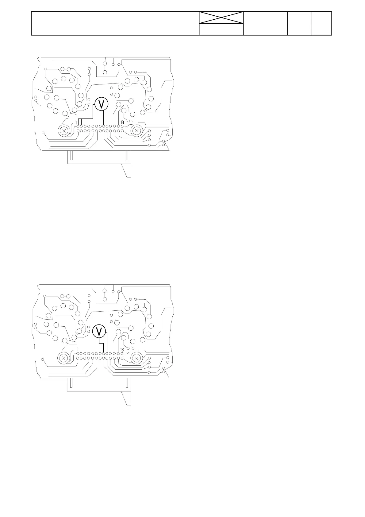
5. Checking DBC/slip control selector S12E
Picture e) Measure voltage between pin 8 and pins 1
(DBC)and2 (slip control) with all selector positions:
Position Pin 1 Pin 2
O F F 4 , 5 --- 5 , 2 V 0
DBC 0 0
DBC+slip control 0 4,5---5,2 V
Slip control 4,5---5,2 V 4.5---5,2 V
Note! If the measured values in point s 2 --- 5 deviate from
the given values, the fault lies in the switch panel circuit
card which should be changed.
6. Checking lift/lo wer switch S10E
Picture f. Measure voltage between pin 8 and 9 in all
rocker switch positions:
Position Pin 9
Lowering position 3,0---3,4 V
Middle position 4,3---4,8 V
Transport position 6,0--- 6,6 V
Note! If the measured values deviate from the given values,
check the switch connector. If the values are further incor-
rect, the fault lies in the circuit card which should be
changed.