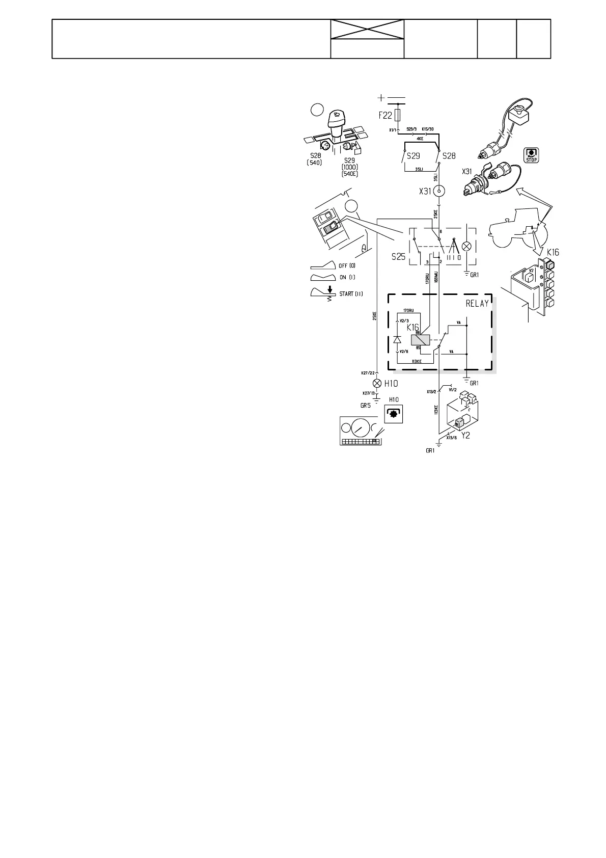
Picture 8. PTO control. The system is supplied via the igni-
tion switch and fuse F22.
248
Model Code Page
31. Autocontrol II
1. 1. 1994
6000--8750 311 10
D. PTO control
Checking function:
Make sure that the plug is fitted in the rear emergency socket.
Move the control lever in the middle position. Check that the
PTO rocking switch front edge is depressed (OFF). Switch off
tractor current. Start the engine and let it run at idling speed.
--- Move the PTO lever to the foremost position (540) at which
time the indicator light should come on. The PTO shaft
must not rotate.
--- Move the lever to the middle position at which time the ind.
light goes out
--- Move the lever to the rear position (1000 or 540E) and the
ind. light should come on. The PTO shaft must not rotate.
Move the lever back to the middle position and the ind.
light goes out.
This shows that:
--- ind. light switches S28 and S29 functions
--- indicator light functions
--- Move the lever to the front position (540). Ind. light comes
on.
--- Turn the PTO rocking switch to the middle position (ON)
--- Depress the rocking switch rear edge (START). The PTO
shaft begins rotate and the rocking switch is returned to
the middle position (ON) by the spring.
This shows that:
--- PTO control relay K16 functions
--- solenoid valve functions
--- Depress the rocking switch front edge (OFF)
--- PTO shaft stops to rotate
--- Turn the switch to the middle position. The shaft must not
rotate. Depress the switch rear edge at which time the
shaft starts to rotate.
This shows that:
--- PTO rocki ng switch functions
--- Remove the plug from the rear socket at which time the
shafts stops rotating. Also the indicator light goes out.
--- Refit the plug. The shaft must not rotate but the ind. light
comes on.
--- Depress the switch rear edge and the PTO shaft must start
to rotate.
This shows that:
--- PTO emergency stop functions
--- relay K16 functions
--- S t o p t h e e n g i n e .
--- Start the engine. The PTO shaft must not rotate although
the lever is in the engaged position
--- Depress the rocking switch rear edge at which time the
shaft begins to rotate.
--- Move carefully the lever to the middle position. The ind.
light goes out and shaft stops.
--- Move the lever to the front position. The shaft must not
rotate.
--- Depress the rocker switch rear edge after which the PTO
shaft starts to rotate.
This shows that:
--- The PTO automatic stop functions when the main current
circuit is cut off.
--- relay K16 functions
1. PTO control lever (540 ---free ---1000 (540E)
S28: Lever switch
S29: Lewer switch
X31: Emergency stop socket
2. 3---position rocking switch
H10: Indicator light
Y2: Solenoid valve
K16: relay which connects current to the solenoid valve,
when the rocker switch rear edge is depressed (START). Sole-
noid is energised so far as the rocking switch is in the middle
position (ON) and the c i rcuit i s not broken with the lever,
emergency plug or with the ignition switch.
Important! The solenoid valve Y2 is placed under the valve
block on the LH side of the gearbox (see picture). When the
solenoid is energised, pressure oil is directed to the PTO
clutch and the shaft can rotate. The nut at the end of the sole-
noid is magnetic when the solenoid is energised.
1
2