483
Model Code Page
37. Autocontrol 5
1. 8. 2000
370 23
6250--8950
1. 10. 1999
E. Temperature sensors in AC 5 (AC 5.2, see
page 371/13).
1. Gearbox oil temperature sensor B14
A
X13, X19
Note! Thesensorissituatingontheservovalveblockon
theLHsideofthegearbox.
1. If this sensor or its wires have malfunctions, the self---
diagnostics show the following codes:
--- A311 (value over+150˚C, unpossible).
--- A 3 1 2 ( v a lu e b e l o w --- 5 0 ˚C, unpossible).
2.CheckthesensorinthetestmodeFII,seetableb on
page 370/11. Compare the reading with the actual oil tem-
perature.
3. If the tempearture reading is incorrect or it is lacking,
then check the sensor and its wires. Measure the resistance
of the sensor from connector X13 pins 10 and 6:
Resistance values (±1 %):
--- 1600 Ω (± 0˚C)
--- 2000 Ω (+25˚C)
--- 3300 Ω (+100˚C)
4. Change the faulty sensor.
Note! If this sensor is faulty, malfunctions can occur in the
transmission multi---disc clutches (delays or jerks).
Note! If the temperature sensor seems to be OK, but mal-
functions occur, the control unit can be faulty.
2. Outdo o r temperature sensor B17.
This sensor is similar as the gearbox oil temperature sensor
and it is placed in the front part of the tractor on the bracket
for signal horn.
1. If the outdoor temperature reading is faulty or is lacking,
checkthesensorinthetestmodeFII,seetableb on page
370/11.
2. Compare the test reading with the ambient outdoor tem-
perature. If no outdoor temperature value is visible, check
the sensor and its wires .
3. If the reading is incorrect, check the sensor fitting and
measure its resistancefrom connector X19 pins 26 and 37.
Replace the faulty sensor.
Resistance values:
--- 1600 Ω (± 0˚C)
--- 2000 Ω (+25˚C)
--- 3300 Ω (+100˚C)
Note! The function of this temperaure sensor does not
affect the technical function of AC 5.
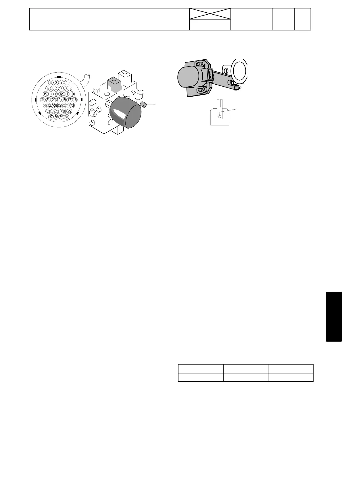
F. Clutch pedal position sensor B16 in
AC 5 (AC 5.2, see page 371/13).
Punch
mark
Note! The position sensor informs the control unit the posi-
tion of the clutch pedal, so that the control unit can control
the clutches.
If the position sensor has malfunctions, the self---diagnosis
shows the following fault codes:
--- f a u l t cod e A314 (signal not within given limits).
--- f a u l t cod e A315 (pedal calibration faulty or pedal limit
switch S9 wrongly adjusted) (switch S2W in the reverse
drive controls (option)).
1. Check the function of the position sensor in the test
mode (table b on page 370/11). If the function is not within
the given limits, check the sensor mounting and wires.
Check also the fitting of the lever on the sensor spindle.
2. Check the adjustment of the limit switch S9 in the test
mode: in the switch---on point the display must show
03...08 (when lifting the pedal). When needed, adjust the
position of the limit switch so that it switches on (click) just a
little before the pedal extreme position. Recheck in the test
mode.
3. Measure, if necessary, the position sensor voltages.
Check the voltages always before calibrating the pedal.
Connect ETV 894 100 between the sensor and its con-
nector (see picture on the next page). If ETV is not avail-
able, measure the supply voltage in the wire loom con-
nector (see picture on the next page). Signal voltage can be
measured from control unit A1 connector A1A3/7---A1A3/8
(see page 370/25).
--- measure the supply voltage (+7,7...8,3 V) between pins
1and3.
--- measure signal voltage between pins 1 (ground) and 2
(signal). Ensure that the voltage value changes evenly
when moving the position sensor lever. Adjust the sensor
position if needed. If the position sensor is faulty, fit a new
one and carry out the pedal calibration. Adjust the position
of the sensor.
Clutch pedal
Pedal up Pedal in bottom
Signal voltage 1,5 ---3,0 V 5,3---6,0 V
Note! When necessary, the gas pedal sensor B15 can be
temporarily used as a spare part (similar sensor, remove
the lever). After that the DPS automatic gear change does
not function. Try to adjust the pedal “bottom” value to
5,7---5,8 V and then check that the “upper” position value is
within given limits.
4. Carry out the pedal calibration according to instruction C
on page 370/15.
Note! If the sensor and its wires seem to be OK, but mal-
functions occur, the fault may lie in the control unit A1. Se-
cure the screw, which fasten the arm to the sensor spindle
with Loctite 222.