119
Model Code Page
37. Autocontrol 5 / 5.2
1. 8. 2000
370 5
6250--8950
1. 9. 2002
2. Fault tracing
A. General
AC 5 / 5.2 unit has an in---built function for self---diagnosis. If fault/faults appear in the AC 5 when working with a tractor, the
fault code of the fault in question is shown in the diplay. In this instruction is shown a table in which there are listed all fault
codes and corres ponding faults. In this way can be localised the fault and possible repair works can be carried out.
In addition, AC 5 / 5.2 unit has an additional diagnostic mode. By pressing certain tractor switches and buttons in a correct
order (instructions later), the display can be activated into the test mode, in which the diplay shows technic al values of vari-
ous electrical components when components in questio n are acti vated. Later in this instruction are shown tables which show
the correct technical values of the components. These values are compared with the actual signals in the displ ay so that
possible incorrect functions can be verified.
In the same way the diplay unit can be activated into the setting mode, in which can be done various settings of the AC 5
components. The setting instructions are shown later in this instruction. In section 4 (components) are given instructions to
measure with a multimeter. With the aid of these instructions the components can be c hecked and verified a faulty compo-
nent.
NOTE! On page 370/7 there are shown working orders för the fault tracing.
B . S e l f --- d i a g n o s i s
The self ---diagnosis of AC 5 / 5.2 follow up possible faults in the system (when the current is switched on) and show a fault
code, which appears in the lower display block (also a book image and the symbol of the module in the middle display block
areblinking,whenthefaultcodeisshown).
FAULT GROUPS: FAULT TYPES:
A: analog input (position and temp. sensors) 1=short circuit or cut
P: proportional output (proportional valves) 2=cut
d: digital input (switches) 3=value not in permissible limits
F: frequency input (rpm sensors) 4=multi---disc clutch is slipping
L: logical fault (slipping clutch)
All fauts are numbered with running numbers (01---99). In addition, fault type is shown with numbers (1---4).
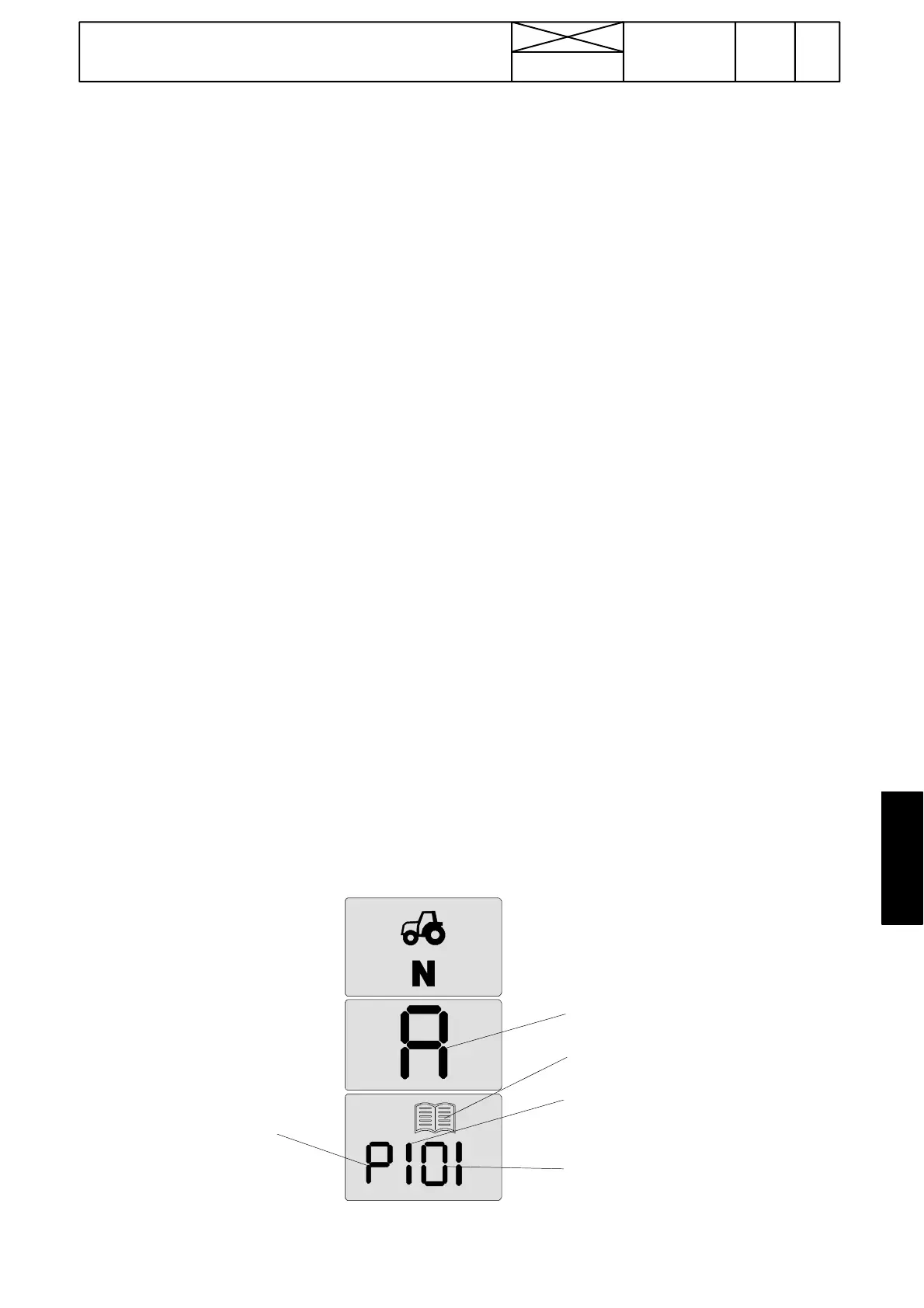
FAULT CODES: (e.g. P101)
The fault code is shown in the display diagnosis block (lower) in four display segments as follows:
--- The first segment from the l eft s hows the fault group (A, P, d, F or L).
--- The seco nd segment from the left shows the fault type (1 --- 4 )
--- The two RH side segments show the order number of the fault (01 ---99).
Note! When the fault code is shown, the symbol of the module is shown in the middle block (A=AC 5 / 5.2), which the fault
has been found.
When the self ---diagnosis shows the fault code, the book image is flashing in frequency of 2Hz.Iftwoormorefaultsare
found simultaneously, the codes of different faults are shown three seconds by turns. When the current is switched off, the
fault code memory is erased. If a fault code has been found, the driving speed or out door temperature cannot be seen in the
lower display block. Also number of the quick---shift gear cannot be seen.
FAULT TYPE: 1=short c ircuit or cut
FAULT CODE:
01= Proportional valve P1 of DPS
FAULT GROUP:
P=proportional output
Module A=AC 5
Book symbol is shown together
with fault code.
IMPORTANT! Escaping from the fault code mode is done by switching off curre nt with the starter switch, when the fault codes
exit from the display block.
AC 5.2 has a fault code memory, in which there are stor ed 3 lates t fault codes with running hours, see page 371/6.