165
Model Code Page
37. Autocontrol 5.2 (K41107---)
1. 8. 2000
371 9C
6250--8950
1. 9. 2002
F. Counter functions in AC 5.2
There are 12 pcs counters in the test mode menu (see page 371/7). The counter symbols are placed below the symbols for
the proportional valves, see table below:
F
A
d
P
C
NOTE! The counters does not function
in all units. This is not a fault, which co-
uld cause the replacement of the unit.
Symbole in
display
Te s t p o i n t
b Number of engagements of F---clutch
F Time in hours how long time the F ---clutch
has been engaged (pressurised)
(r)
Number of engagements of R ---clutch
A Time in hours how long time the R---
clutch has been engaged (pressurised)
C Number of engagements of DPS1 ratio
U Time in hours how l ong time the DPS 1
clutch has been engaged (pressurised)
J Number of engagements of DPS2 ratio
P Time in hours how lo ng time the DPS 2
clutch has been engaged (pressurised)
E Number of engagements of DPS3 ratio
d Time in hours how long ti me the DPS 3
clutch has been engaged (pressurised)
H Number of engine starts
L Time in hours how long time the ACV
control unit has been active.
The counters are accessible after activating the test mode
and by stepping in the menu with the aid of the DPS push
buttons.
Note! When the curr ent is switced on with the ignition
switch, the default ratio is DPS1. The value in counter H
increases with one digit every time the engine revs rise over
400 r/min. Counter L shows the total running hours of the
control unit. If the c ounter reading is smaller than tractor
running hour s, a new control unit has been fitted later on
the tractor.
Note! Reading counters is happened without a separate
confirmation. The counters cannot be zeroed in service. If
the control unit is reprogrammed, the counter values re-
main in the control unit memory. In the spare part control
unit the co unters have been zeroed.
The greatest value of the hour recorders is 9999 after which
the counters are zeroed. Counters are switched on always
when current is switched on in the control unit.
The readings of the counters are shown shor tened as follows:
--- the LH side display segment shows the counter symbol
--- the two intermediate segments show the two first significant
digits of the reading
--- the RH side segment shows the number of zeroes.
E.g. b 23 3 means that driving direction forwards has been
engaged 23000 times.
Last Number of
digit zeroes
0 ---
10
200
3 000 (thousands)
4 0000
5 00000
6 000000 (millions)
Timerecorderreadings (F,A,U,P,d,L)arealsoshowninthe
same way.
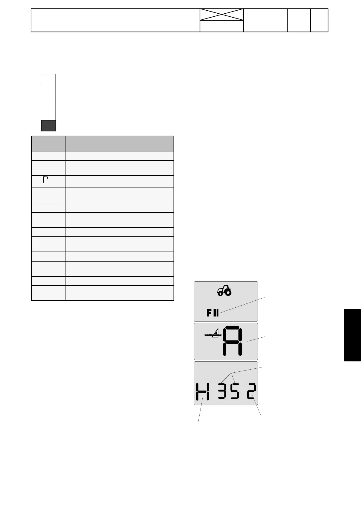
Example:
Test m od e
symbol
Module
H= number o f engi-
ne starts
35=number of
engine starts,
two first digits
2 =Numberofzeroes
i.e. H = 3500 times.
Note! The counters can be used in connection with mainten-
ance or repair works, when e.g. estimating life time of various
components or clutch wear etc.