511
Model Code Page
37. Autocontrol 5.2 (K41107---)
1. 8. 2000
371 7
6250--8950
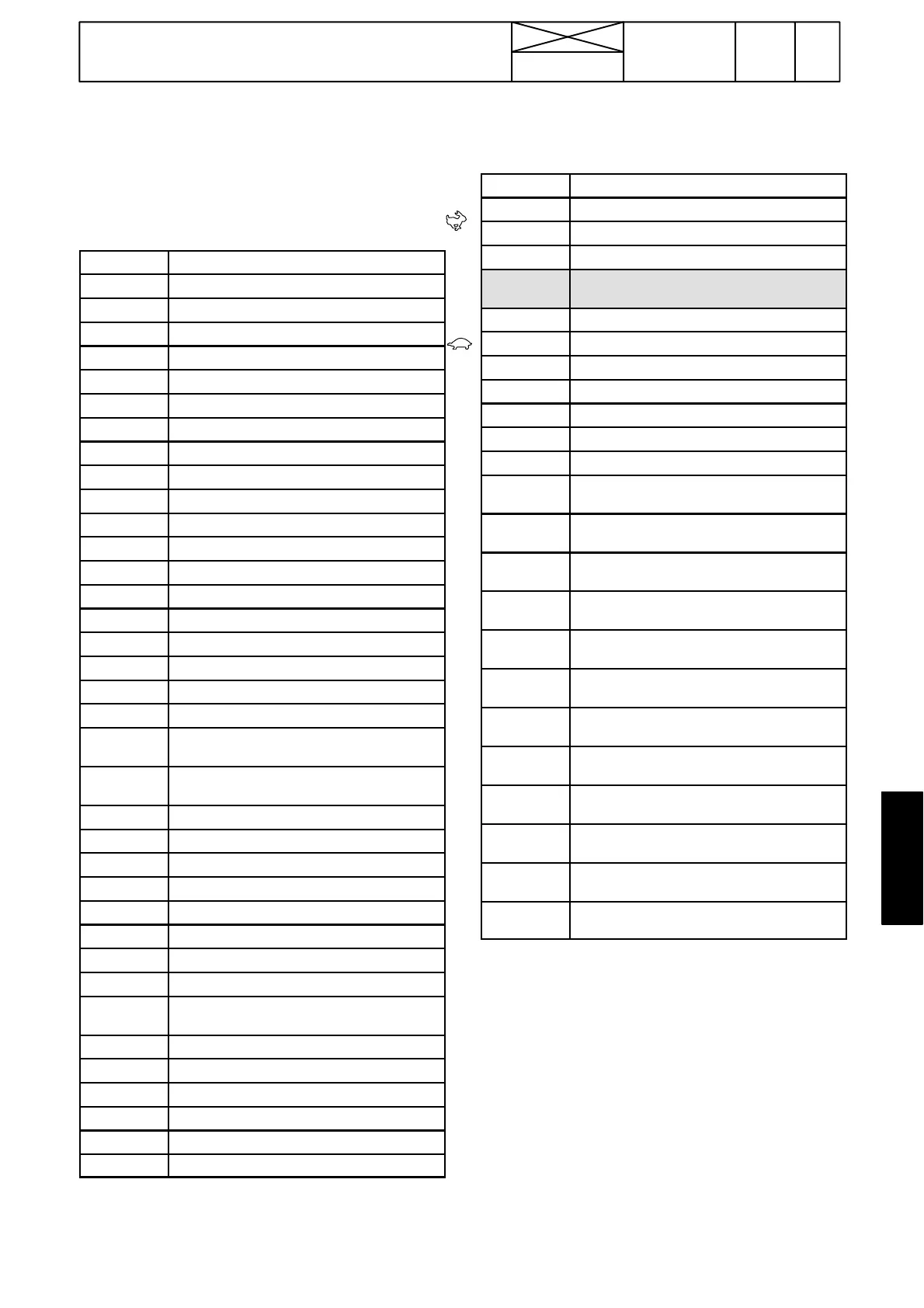
2. Tests
Note! The correct electric signals from sensors and swit-
ches have been shown in the tables on pages 371/8---9C.
A.TestmodeFIImenuinAC5.2
Note! Activating the test mode, see page 370/8.
F7
Shuttle rotation direction *)
F6 PTO revs *)
F5 Shuttle rotation speed (lower sensor) *)
F4 Shuttle rotation speed (upper sensor) *)
F3 Reserve
F2 Driving speed *)
F1 Engine revs *)
A8 Rear clutch pedal pos. sensor signal, V
A7 Rear clutch pedal position %
A6 Front clutch pedal pos. sensor signal, V
A5 Front clutch pedal position %
A4 Gas pedal pos. sensor signal, V *)
A3 Gas pedal positon % *)
A2 Gearbox oil temperature
A1 Outdoor temperature
d24 Brake pedal position (brake light switches)
d23 AutoTraction switch (N ---Auto)
d22 Parking brake, reverse drive controls
d21 DPS pre---programmming button, reverse
drive controls
d20 Clutch pedal limit switch, reverse drive
controls
d19 Direction R, lever , reverse drive controls
d18 Direction F , lever, reverse drive controls
d17 PTO ---start, button on rear mudguard
d16 Parking brake, front controls
d15 PTO stand---by switch
d14 Seat direction (TwinTrac only)
d13 PTO---speed 2 (lever in rear position)
d12 PTO ---speed 1 (lever in front position)
d11 DPS pre---programming button, front cont-
rols
d10 Direction R, lever, front controls
d09 Direction F, lever, front controls
d08 DPS auto/man
d07 DPS auto1/auto2
d06 Clutch pedal limit switch, front controls
d05 Seat switch 1)
d04 PTO---startswitchincab
d03 H i S h i f t --- bu t t on s
d02 DPS---button, down
d01 DPS---button, up
99 99 Parameter number and program num-
ber. Start level.
P1 DPS---prop. valve 1 (clutch C1) current *)
P2 DPS---prop. valve 2 ( C2) ottama virta *)
P3 D P S --- p r o p o 3 ( k y tk i n C3) otta m a v ir t a * )
P4 Shuttle prop. valve (forwards) current *)
P5 Shuttle prop. valve (rearwards) current*)
P6 PTO prop. valve current *)
b Counter: informs how many times F---di-
rection has been engaged.
F Counter: informs how many hours F---di-
rection has been engaged.
r Counter: informs how many times R ---di-
rection has been engaged.
A Counter: informs how many hours R---di-
rection has been engaged.
C Counter: informs how many times DPS1
(C1) has been engaged.
U Counter: informs how many hours DPS1
(C1) has been engaged.
J Counter: informs how many times DPS2
(C2) has been engaged.
P Counter: informs how many hours DPS2
(C2) has been engaged.
E Counter: informs how many times DPS3
(C3) has been engaged.
d Counter: informs how many hours DPS3
(C3) has been engaged.
H Counter: informs how many times the engi-
ne has been started.
L Counter: informs how many hours AC 5.2
control unit has been energised.
*) Engine must be run
1) If detector switch S60 does not function, it can temporarily
be by---passed by connecting switch wires with an auxiliary
wire (connector beside the seat holder). The switch must be
changed and the auxiliary wire removed as soon as possible
(safety).