6600, 8000, 8100 (660477--- ), 8400
6100, 6300, 6400 (660477--- )
6100--- 8100: ---660476
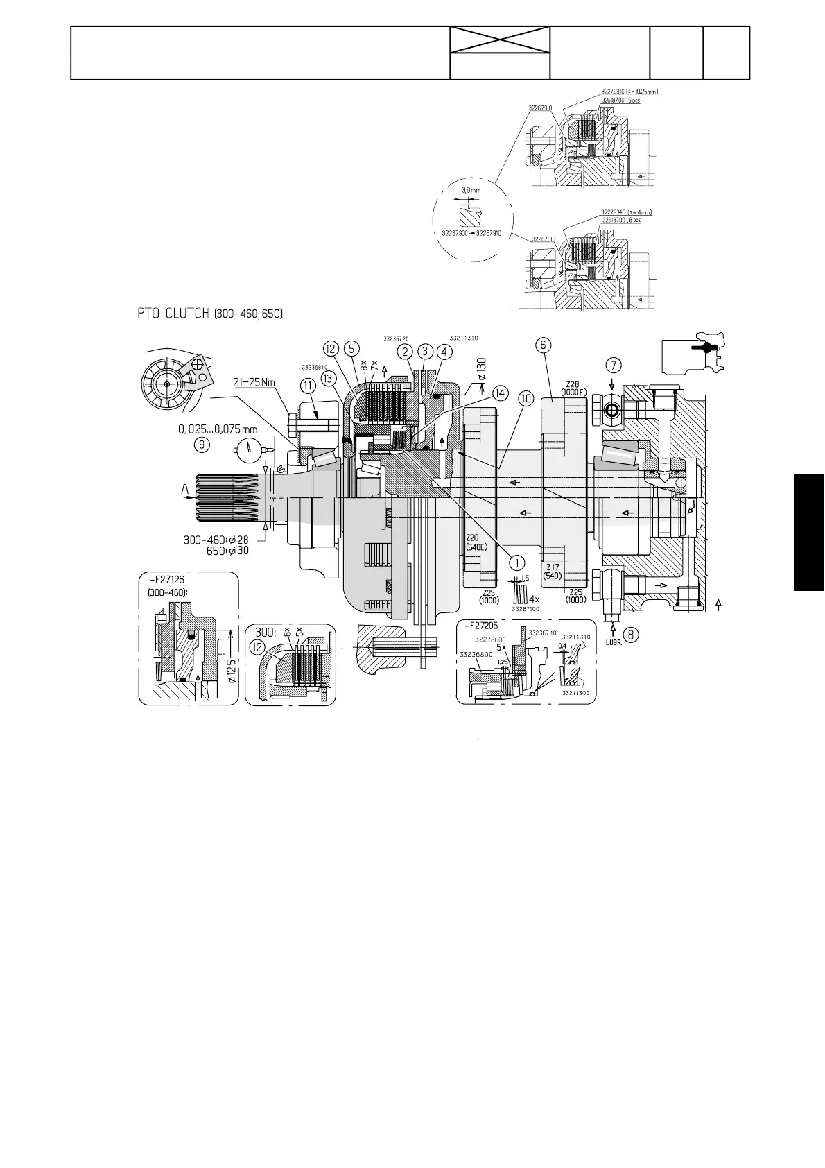
Figure 6. PTO clutch
1. Cup springs (5 pcs)
2. Pressure plate (modified for spring 14)
3. PTO brake disc
4. Piston
5. Shaft / clutch drum
6. Shaft
7. Pressure oil to clutch
Pressurised oil to the clutch is conducted from the servo
valve block (on gearbox LH side) via internal piping to the
rear end of the PTO clutch shaft (6) and onwards via dril-
ling to the oil space behind the piston (4)
8. Lubricating oil
9. Adjustment of PTO clutch shaft bearing cleareance
10. Fastening with Loctite 601
11. Loctite 242 on the threads
12. Support ring (6 friction discs: s=10,25, 7 pcs: s=7,4
mm, 8 pcs: s=4 mm
13. Hub
14. Cup spring (on latest models)
225
Model Code Page
46. Power take ---off
1. 9. 2002
6000--8750 460 9
1. 8. 1998
PTO multi---disc clutch
When there is no oil pressure in the clutch (solenoid valve un-
energized), cup springs (1) press plate (2) against brake disc
(3) causing brake action.
When pressure is connec ted behind the piston (4 ), it moves
forwards releasing the brake and engaging via disc pack the
clutch drum (5) to shaft (6) and power is transmitted to the
PTO shaft.
Note!On the latest clutches, the clutch housing (5) has been
reinforced with a metal ring.
A number of the clutch discs and disc material have been
changed.
Number of the discs, see technical data on page 460/2.Con-
cerning repairs of the earlier clutches, see page 462/3 and
pictures above.
HeavyDutyPTOclutch,seepage460/6A.
Note! In transmission 650 the clutch drive shaft diameter is 30
mm. In other transmissions (300, 460) the diameter is 28 mm
Note! From ser. no. F27127 incl. the piston of the HD clutch
and the standard clut ch is the same (ø 130 mm). At the same
time the piston seal was changed into an o---ring. From ser.
no. H11438 incl. the dimensions and shape of the piston have
been changed. This modification helps to ensure that the PTO
shaft stops when the PTO is disengaging.