525
Model Code Page
37. Autocontrol 5.2 (K41107---)
1. 8. 2000
371 15
6250--8950
5. Others
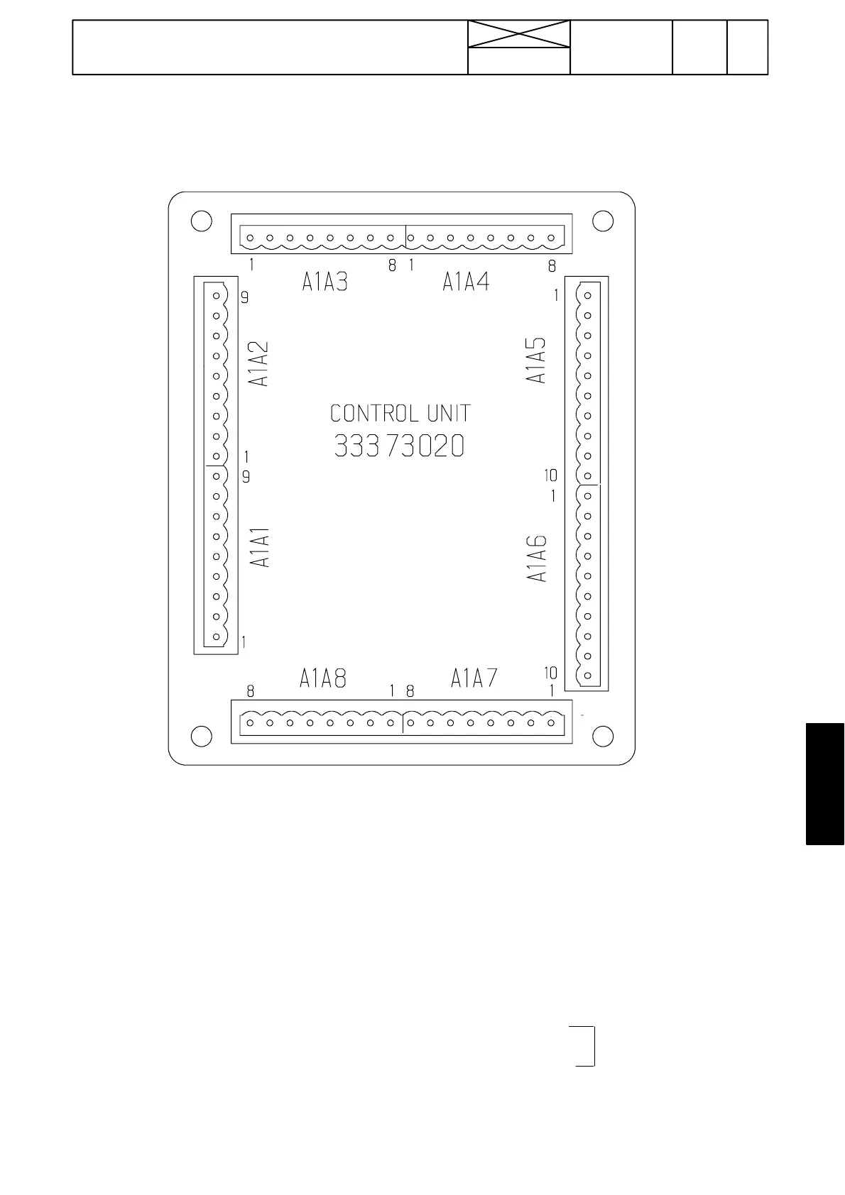
A. AC 5.2 control unit, connectors:
DIGITAL INPUTS:
d01=DPS up (S23)
d02=DPS down (S23)
d03=HiShift (S45)
d04=PTO start in cab (S25)
d05=seat switch (S60)
d06=clutch pedal, front (S9)
d07= DPS Auto1/Auto2 (S47)
d08= DPS auto/manual (S47)
d09 = Forwards F, front (S40)
d10=Rearwards R, rear (S41)
d11=DPS pre---progr., front (S51)
d12=PTO speed 1 (S28)
d13=PTO speed 2 (S29)
d14=direction of seat (S3W)
d15=PTO standby (S25)
d16=hand brake, front (S15)
d17= PTO start, mudguard (S1A, S2A)
d18= Forwards F, rear
d19= Rearwards R, rear
d20=Clutch pedal, rear (S2W)
d21=DPS pre---progr., rear
d22=handbrake, rear
d23=traction control (S76)
d24=Brake pedal switches
ANAL OG INPUTS:
A1=outdoor temp (B17)
A2=oil temp (B14)
A3=Gas pedal, signal (B15)
A4=front clutch pedal, signal (B16)
A5=rear clutch pedal, signal (B1W)
A6=reserve
FREQUENCY INPUTS:
F1=engine speed (B11)
F2=gearbox speed (B6)
F3=reserve
F4=shuttle speed 1 (B12)
F5=shuttle speed 2 (B13)
F6=PTO speed (B7)
OUTPUTS TO PROPORTIONAL VALVES:
P1=DPS solenoid 1 (Y4)
P2=DPS solenoid 2 (Y6)
P3=DPS solenoid 3 (Y17)
P4=F---solenoid (Y11)
P5=R---solenoid (Y12)
P6=PTO ---solenoid (Y2)
P7=starter interlock (K52)
P8=4WD automatics
DATA TRANSFERRING CHANNELS:
CAN 1 HI *)
CAN 1 LO *)
CAN SHIELD *)
CAN 2 HI *)
CAN 2 LO *)
CAN SHIELD *)
GND
Rx RS---232
Tx
*) CAN transferring channels are not in use
for the present.
DIGITAL OUTPUTS:
DO 1=LCD display
DO 2=LCD display
DO 3=LCD display
DO 4=LCD display
DO 5=parking brake
DO 6=PTO pilot light (H10)
P8
P7
DO 6
P6
DO 5
P5
DO 4
P4
DO 3
P3
DO 2
P2
DO 1
P1
GND
GND
d17
d18
d19
d20
d21
F1
d22
F2
d23
F3
d24
F4
GND
F5
GND
F6
GND
+12 V
A5
A6
d03
d04
d05
d06
d07
d08
d09
d10
d11
d12
d13
d14
d15
d16
A1
A2
V
ref (+5 V)
A3
GND
V
ref (+5 V)
A4
GND
d01
d02
CAN 1 HI
CAN 1 LO
CAN SHIELD
CAN 2 HI
CAN 2 LO
CAN SHIELD
GND
GND
Rx
Tx
(Programming)
Supply
Vref (+5 V)=supply to pedal pos.
sensors.