Adjuster stop
1131
Model Code Page
80. Cab and shields
8. 11. 1990
6000--8750 811 1
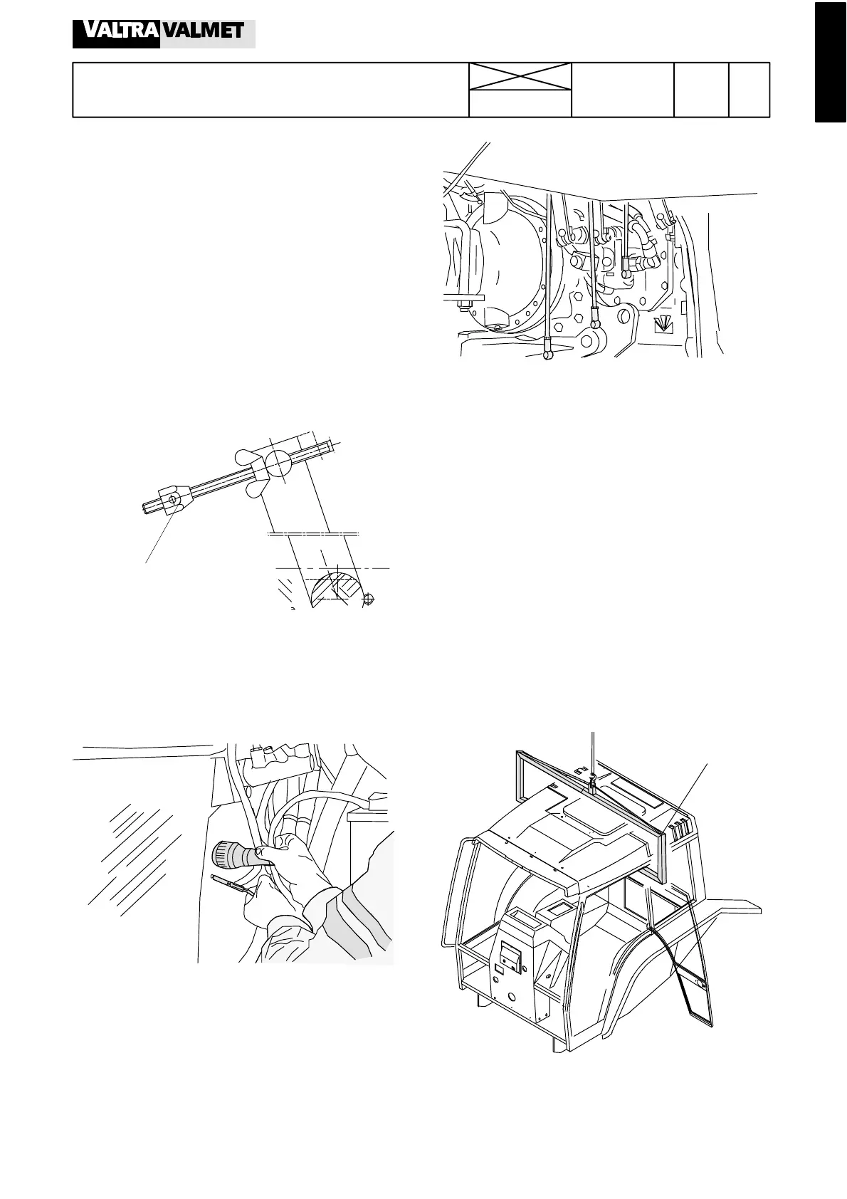
1. Removing and fitting cab
Note! If the garage has not enough lifting space, first remove
the rear wheels. Then detach the auxiliary hydraulic valve
block bracket on the gearbox (work through access hole on
the mudguard). Then detach the quick---action couplings
from their bracket and fasten valve blocks and pipes to the
cab with wires. Now it is not necessary to lift the cab very
much.
A. Removing cab
1. Remove the engine hood plates. Disconnect the battery
cables.
2. Detach the following in front of the c ab on the LH side:
--- adjusting rod from the clutch lever (measure the position of
the adjuster stop for easier fitting)
--- stop control cable from the injection pump
3. Detach the following parts from the cab front wall:
--- socket and the accelerator pedal cable
--- steering valve bracket screws
--- cab earth cable
4. Disconnect the cable from the starter motor. Disconnect the
windscreen washer hose and cable shoe.
4. Drain a little engine coolant through the motor block plug
and disco nnect the heate r hose front ends from the engine.
5. Disconnect t he following parts on the RH side:
---shifterrodsfromthegearleverlowerends
--- shifter cables from the selector levers and from the lower
ends of the gear levers
--- ground speed PTO cable from its selector lever (if fitted)
--- solenoid valve leads from the control valve for the hydraulic
lift
6. Disconnect the following parts at the rear of the tractor on
the RH side:
--- hydraulic lift sensor connectors
--- PTO control cable lower end
--- pick---up hitch release co ntro l lower end
--- lifting link gear control rod lower end
7. Disconnect the following parts at the rear of the tractor on
the LH side:
--- sole noid valve lead connector
--- sensor wires from the servo valve block
8. Unscrew the brake cylinder fixing screws and release the
parking brake cable. Support the brake cylinders.
Note! The brake pipes can also be disconnected at the joint
under the cab floor on the LH side. Now it is not necessary to
detach the brake cylinders.
ET 894 110
9. Unscrew the cab front and rear attaching bolts. Fit the tool
ET 894 110 on the rear edge of the door opening and lift the
cab carefully.
Note! Make sure that the auxiliary hydraulic valve levers do
not prevent lifting. Remove, if neces sary, the lever knobs.