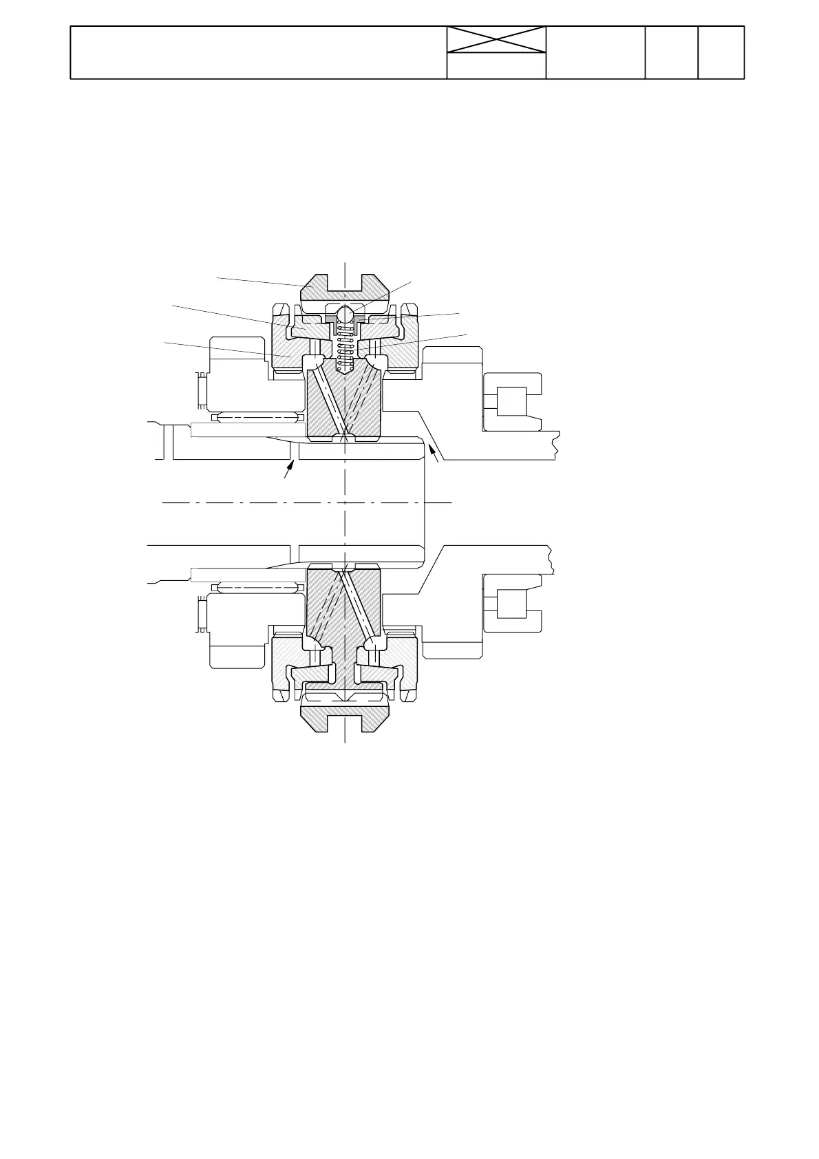
A. Sliding coupler
B. Synchronizing cone (2 pcs)
C. Coupler (2 pcs)
D. Ball (3 pcs)
E. Shoe (3 pcs)
F. S p r i n g ( 3 p c s )
678
Model Code Page
42 Gearbox
15. 5. 1993
10420
6000--8750
15. 6. 1992
Synchronization
Synchronizing cones
On input shaft (couplers for gears 1---2 and 3---4): ø82 mm,
steel
On bevel pinion shaft (coupler for ranges M and H): ø90 mm,
steel
The synchromesh units can be fitted either way. The synchro-
mesh units on the input shaft are interchangeable and can be
fitted either way. Measuring synchronizing cone wear and as-
sembling the unit, see page 423/7.
A
B
C
D
E
F
Figure 10. Synchromesh unit
Engagement
The axial movement of the sliding coupler(A) pressesthesyn-
chronizing cone (B) against the male taper on the coupler (C)
by means of the balls (D) and shoes (E). The different speeds
of the components to be coupled together produces stagger-
ing of their relative positions, limited by stops, which in turn
causes the chamfered teeth on the synchronizing cone (B) to
press against the sliding coupler (A), thereby preventing any
relative movement of this coupler. The pressure exerted by
the sliding couple r (A) and the staggered position of the syn-
chronizing cone (B) creates axial pressure between the tap-
ered friction surfaces on the synchronizing cone (B ) and the
coupler (C) by means of the chamfers on the teeth. This axial
pressure gradually reduces the difference in speeds in order
to achieve synchronization.
Once, the speeds have been synchronized, the sliding
coupl er (A) continues to exert pressure against the synchro-
nizing cone (B) and pushes it backwards until the teeth in
coupler (A) are opposite gaps between the teeth on the syn-
chronizing cone (B). At this point the resistance, which had so
far prevented the sliding coupler (A) from moving, is over-
come and the sliding coupler (A) engages silently with the
teethinthecoupler(C)
Neutral position
The sliding co upler (A) is in the middle position. Balls (D) are
pushed into the V shaped groove in the sliding coupler (A) by
springs (F). The gears can turn freely on the shaft. The sliding
coupler (A) is locked in this position by three balls (D) held by
springs (F).