120
Model Code Page
22. Fuel system
1. 6. 1999
8050--8550 223
12
1. 8. 1998
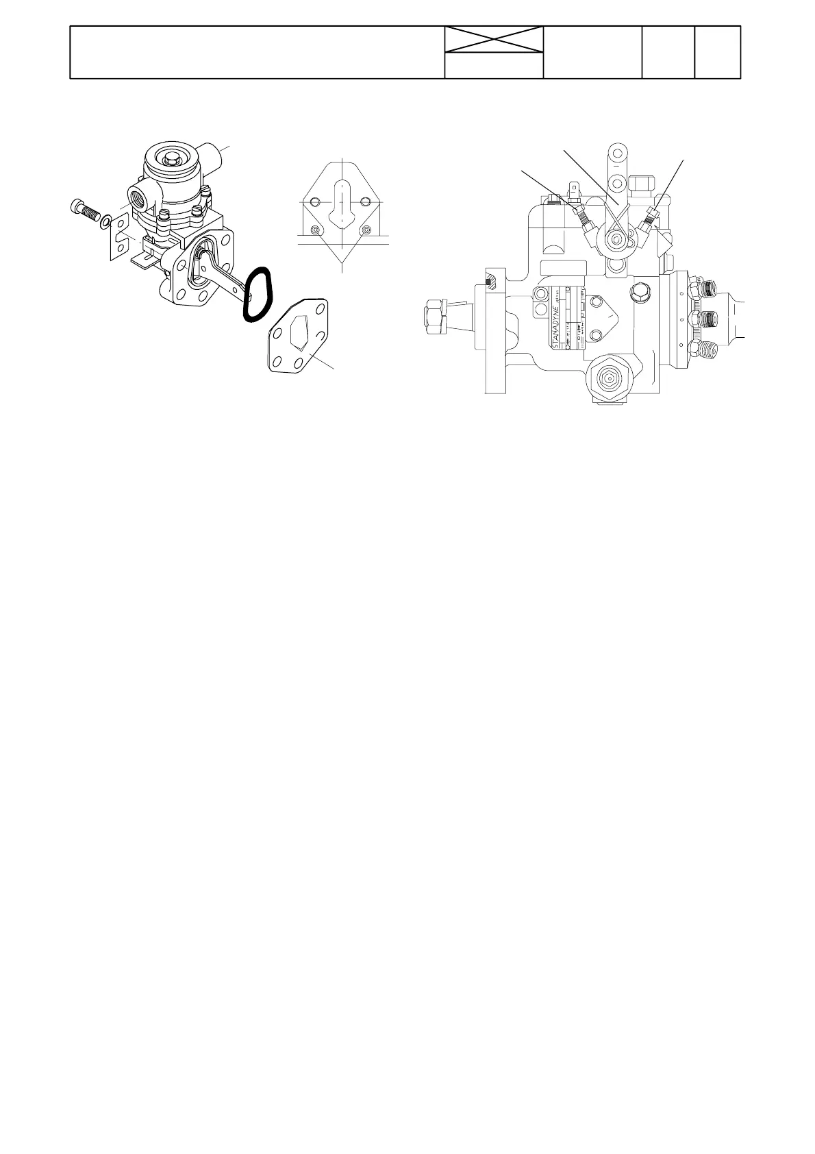
Fitting new fuel feed pump
A
4
--- Remove the o ld feed pump and fuel pipes
--- Clean the sealing surface on the cylinder block
--- Place an o---ring into the groove on the pump
--- Engines with two fixing bolts: apply sealing compound
T61050 (Weicon Lock AN---305---74) o n the cylinder block si-
deoftheflange4(iffourfixingholestheflangeisnotfitted.
--- Apply sealing compound also on the threads of the bolts
( 2 pcs or 4 pcs) and fasten the pump. Tightening torque is 30
Nm.
--- Bend the pipe between the filter and pump or use a flexible
pipe which incl. in the kit.
Note! If the cylinder block has already four threaded bolt ho-
les , remove plugs from poi nts A, and fasten the pump with
four bolts (sealing compound on the threads of all bolts) wi-
thout the intermediate flange (4).
Sealing compound (50 ml)......6909 30030
Sealing compound (250 ml).....6909 30016
E. Injectors
Injectors are checked and serviced according to instructions
G --- J on pages 223/5 ---7.
The opening pressure of the injectors, see tables on pages
220/14---15.
Adjustment is achieved by changing the shims. The thickness
of the shims varies from 1.00---1,90 mm and they are available
in increments of 0,05 mm. A thicker shim will raise the opening
pressure while a thinner one lowers it. A difference in shim
thickness of 0,05 mm changes the opening pressure by ap-
prox. 5,0 bar. As the opening pressure of the injector drops
slightly after adjustment, the opening pressure should be set
toapproximately 10 bar above thevalue given in thespecifica-
tions. This value applies both to new and used injector.
F. Adjusting low idling speed
Revolution lever
Max. revs
Low idling speed
The low idling speed can be adjusted with a limiting screw in
front of the revolution lever. The adjusting screw for max. revs
has been sealed. This adjustment has been done in the fac-
tory, and adjustment of max. revs afterwards is prohibited.
Note! The throttle cable is attached to the revolution lever
lower hole. To the upper hole is fastened a return spring.
Other information
The injection pump housing upper c over has been sealed to
prevent adjustment of engine output afterwards. Also the stop
solenoid is fitted under this cover. If the injection pump is dam-
aged during the warranty period, a replacement pump must
be fitted. After the warranty period it is recommended, that all
pump repairs are made by an authorised Stanadyne work-
shop.
G. Bleeding Thermostart system
Always remove air from the glow plug fuelpipe when the pipe
or reservoir has been emptied during repair work etc. This
preventsdamagesto the glow plug causedby lack of fuel dur-
ing starting.
1. If the reservoir is empty, fill it e.g. with a drip pot through the
breather hole on the reservoir.
2. Open the glow plug pipe connector and drain fuel from the
pipe. Connect the pipe.
H. Delivery pipes
On tractors 8050, 8150, 8450 and 8550 the delivery pipe ap-
pearance is the same, but on tractors 8050 and 8150 the inner
diameter of the pipes is smaller than on tractors 8450 and
8550.
For this reason the pipes have different spare part numbers.
Delivery pipes for 8450 and 8550 tractor (greater I.D.) have
been labelled with tape.