139
Malli Koodi Sivu
37. Autocontrol 5 / 5.2
1. 9. 2002
370 19B
6250--8950
L. Check of the gas pedal sensor calibration with the computer,AC5and5.2
The check with the computer, if:
--- Calibration has not succeeded.
--- Calibration is correct but DPS has malfunctions (specially
low revs models 6750 and 8350).
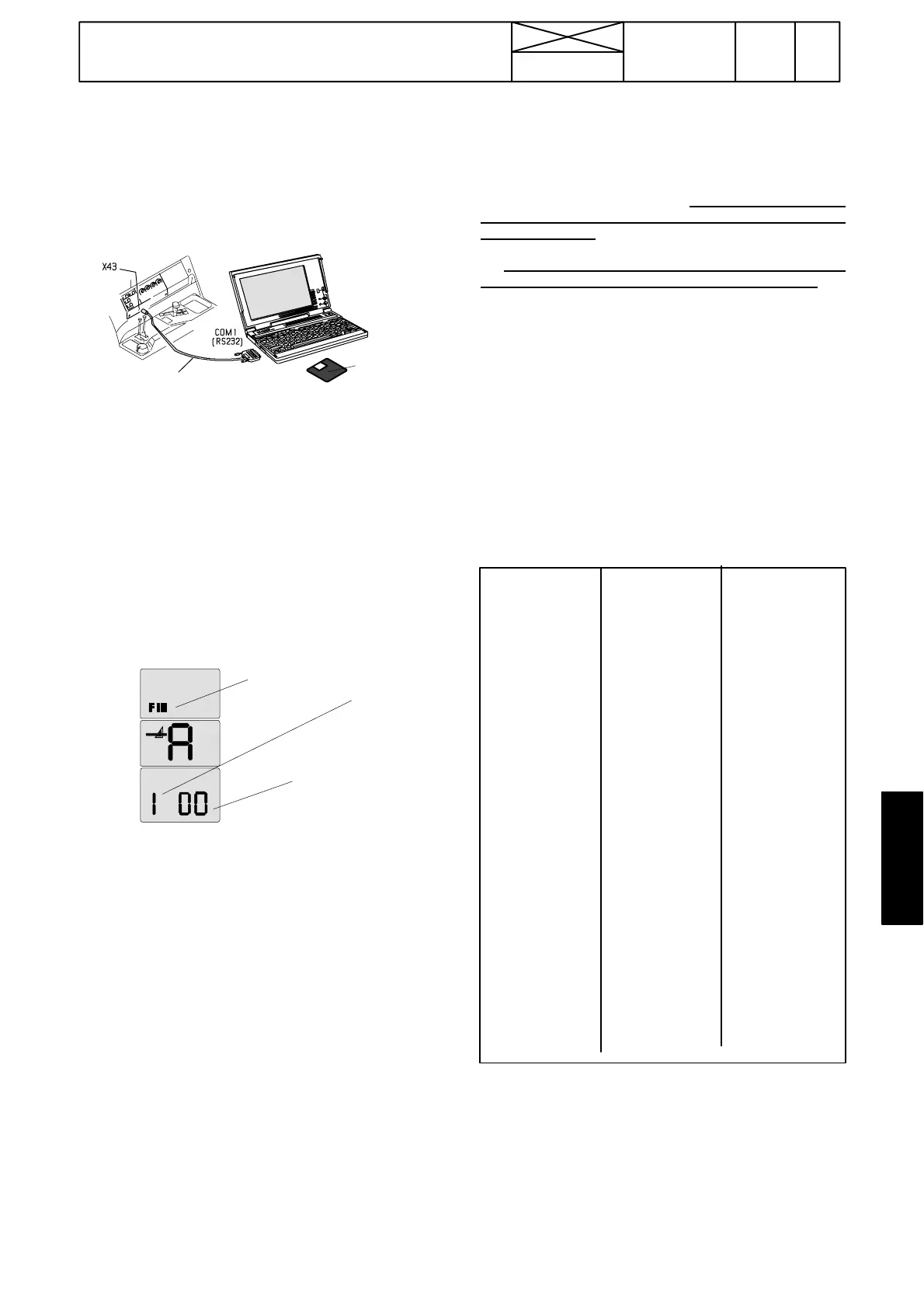
1. Switch the power of the tractor off. Connect a programming
cable to the PC and to the connector X43.
tai COM2
337 006 00, L=1,5 m tai
337 006 10, L=8,0 m
340 422 60
2. Turn the PC’s power on and start Windows. Insert an AC5
programming diskette to the PC’s disk drive A:> and choose
“ VALT_TRM95_COM1 ” and start the program according to
instr. B.2 on page 370/ 24B).
3. Switch the power of the tractor on. Text “ RESET ” or
“Loader 0.4” appears if the communication is OK. In case of
malfunction try once more.
4. The computer is now ready to receive information about the
calibration. Do the calibration normally ac cording the
following instructions.
5. Activate the setting mode FIII according to instr. A on page
370/14.
6. Select in the setting mode symbol 1 (gas pedal calibration)
with the DPS push buttons (in the speed gear lever knob) and
confirm it with the DPS pre---programming button (see page
370/14)
FIII=setting
mode sym-
bol
1=gas pe-
dal calibra-
ting mode
Blinking
00=calibration
can be done
7. When the gas pedal calibration has been selected and con-
firmed (1 is visible in the LH side segment),
digits 00 start to blink in the two RH side segments (2 Hz). This
indicates that the calibrating can be done.
8. Set the mechanical gears in neutral (engine at low idling).
Raise the engine revs evenly and gently with the throttle lever
up to max. revs taking about 10 seconds, however all the time
the revs must increase. When the max. revs have been re-
ached, wait about 3 seconds and press the HiShift button.
At which time the control unit reads values in the cal ibrating
points and saves them in to memory. Lower the low idling
speed. After the successful calibration digits 01 appear in the
two RH side segments. If the calibration is not successful, start
the calibration again and raise the revs slower once again du-
ring 12---15 seconds with the hand throt tle lever.
NOTE! If the calibration has failed (00 without blinking in the
two RH side segments), the values are not saved but the
earlier values remain valid. In this case the calibration must be
repeated.
IMPORTANT! The calibrating mode is left by switching the
current off.
9. After calibration is finished the calibration values will appear
on the laptop’s screen automatically, see Ta b l e 1 .Scrollthe
text on the screen if all values are not shown from the top. On
the top of table is the text, “pedal motor”
10. From the values can be seen all the pedal position values
for the control unit and the motor values in rpm. Selected va-
lues of the calibrat i on are below all values. Both all values and
selected values must be correct. If they are correct, an
in-
formation
“ Error0 ” appears, then the calibration is done cor-
rectly, see
Ta b l e 1 .
11. If the calibration has not been done correctly information
“ Error ”
appears and amount of the errors, see Ta b l e 2 . This
canhappenifallorselected pedal values do not increase
evenly. This means that if the value is decreasing or there are
the same value twice, the calibration has failed.
12. In table 3 is an example in which calibration appears to
be correct, because of the information “ Error 0 ”. But in the
last row, the value of the engine’s revs is lower than the earlier
value. This can cause DPS malfunctions. Do the calibration
again.
NOTE! Check always that pedal and engine values increase
evenly, although the information “ Error 0 ” appears. It is poss-
ible, that the computer does not find faults.
13. Do the gas pedal calibration again and make sure that
revs are rising evenly (without stop) during calibration.
Other possible faults listed in stage G and in page 370/24.
If “ PEDAL ” ---values do not increase evenly.
--- Check the sensor function in all measuring areas ( e.g. with
oscilloscope FLUKE 123)
--- Check, that the gas pedal is pressed evenly during the
wholecalibrationinthesamedirection.
If “ MOTOR ” ---values do not increase evenly.
--- Check, that the gas pedal is pressed evenly during the
whole calibration in the same direction. (the pressing can be
slowed a little towards the end).
--- Check the function of the engine speed sensor B11 in all
measuring areas.
Loader v0.4 4Mb-
Samples
pedal motor
233 851 rpm
249 934 rpm
267 1016 rpm
291 1104 rpm
335 1271 rpm
358 1360 rpm
383 1448 rpm
405 1529 rpm
431 1610 rpm
455 1697 rpm
477 1785 rpm
502 1868 rpm
527 1954 rpm
528 2035 rpm
530 2001 rpm
Selected
pedal motor
233 851 rpm
267 1016 rpm
313 1187 rpm
358 1360 rpm
405 1529 rpm
455 1697 rpm
502 1868 rpm
528 2035 rpm
530 2001 rpm
Error 0
Loader v0.4 4Mb-
Samples
Pedal Motor
312 869 rpm
327 950 rpm
344 1031 rpm
354 1115 rpm
371 1196 rpm
385 1279 rpm
401 1363 rpm
416 1444 rpm
433 1525 rpm
447 1605 rpm
465 1691 rpm
480 1777 rpm
499 1863 rpm
512 1944 rpm
497 1863 rpm
514 1952 rpm
534 2046 rpm
551 2127 rpm
567 2208 rpm
Selected
Pedal Motor
312 869 rpm
354 1115 rpm
385 1279 rpm
416 1444 rpm
447 1605 rpm
499 1863 rpm
497 1863 rpm
534 2046 rpm
567 2208 rpm
Error 1
Loader v0.4 4Mb-
Samples
Pedal Motor
311 878 rpm
341 960 rpm
356 1045 rpm
368 1125 rpm
377 1208 rpm
389 1290 rpm
414 1378 rpm
434 1465 rpm
451 1558 rpm
464 1641 rpm
473 1728 rpm
488 1817 rpm
530 1916 rpm
551 1996 rpm
563 2078 rpm
572 2161 rpm
580 2245 rpm
609 2335 rpm
Selected
pedal motor
311 878 rpm
368 1125 rpm
389 1290 rpm
434 1465 rpm
464 1641 rpm
488 1817 rpm
551 1996 rpm
572 2161 rpm
609 2335 rpm
Error 0
TABLE 1
TABLE 2
TABLE 3
pedal: gas pedal position motor: engine speed