---122---
K. Extra equipment
K 2.4.2. Brake valve of the trailer
2
1
3
4
4A
4A
5
6
6A
7
8
9
10
8
11
69---125,1
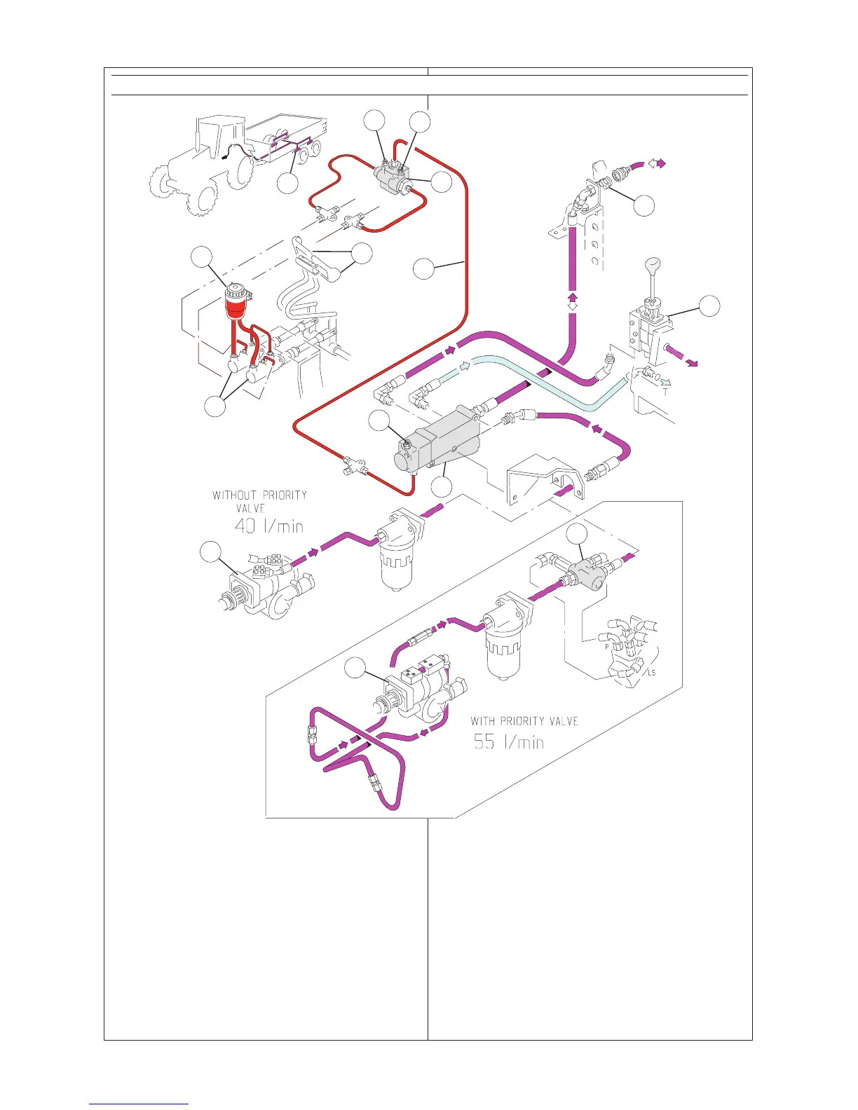
1. The construction of the trailer brake valve:
1 Brake pedals
2 Brake fluid reservoir, common with the tractor brakes
3 Main brake cylinders
4 Release valve, (compensation valve) through the relea-
se valve the control pressure goes to the brake val-
ve (6) only when the both pedals are pressed
4A Bleed nipples of the release valve
5 Control pressure for the brake valve
6 Brake valve
6A Bleed nipple of the brake valve
7 Quick---action coupling for the trailer brake
8 Hydraulic pump
9 Brake cylinders for the trailer
10 Auxiliary hydraulic valves + power lift
11 Priority valve, only in 55 l/min models
The trailer brake valve system makes use of the pressure
of the tractors hydraulic system (pressure ratio1:7,11 ad-
justable) controlled with the brake valve.
2.
Instructions for operating
The trailer brakes are connected to the quick---action
coupling at the rear part of the tractor (7).
NOTE! When using the trailer brakes the brake pedals
must always be locked together when driving on the
road.