---89---
I. Checks and adjustments
equipment. The fuse list is on the component list of the
wiring diagram on page 108.
When you need a continuous electrical supply eg. to the
implement, illumination etc. power can be taken from the
trailer connection (see page 53). With the implement
control system (optional equipment) electrical power to
the optional equipment can be switched on and off from
the driver’s cab.
Power for optional equipment can also be taken from the
spare fuses or unused optional equipment fuses. A
continuous power source can be connected from the
main current pole of the starter motor (on the models with
main circuit breaker, power is switched off with main
switch) through the new fuse.
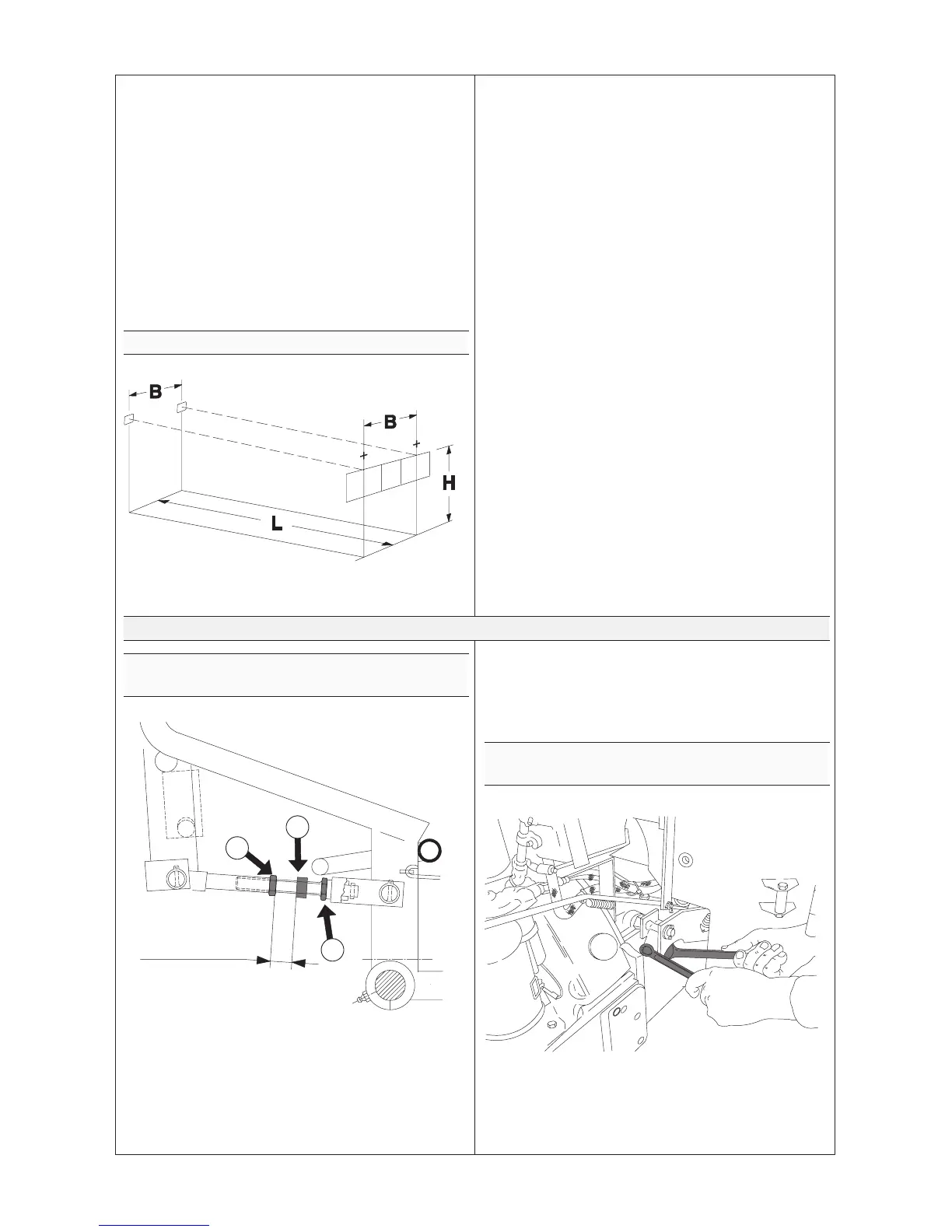
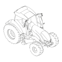
I 2.4. Headlight adjustment
A3565---132
Correct adjustment of the headlights is very important
when running on the public road.
Headlight adjustment can be carried out quickly and
accurately by using an optical headlight adjusting unit. If
no optical instrument is available, adjustment can be done
as follows.
With dipped---beam switched on, the cutoff edge of the
light pattern should come at height H when the tractor is
at distance L. With full---beam switched on, the distance
between the light points should be B. Any necessary
adjustment is done by using the headlamp adjusting
screws.
Measurements:
L = 5 m
B = Center distance between headlights
H = Height of headlights above ground minus
50 mm
If tractor has up lifted full/dipped beam headlights (on the
top part of the cab), the lights have to be adjusted so, that
the light pattern shines on the mark at a distance of 30 m
on even ground.
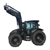
I 3. Power transmission
I 3.1. Adjusting pedal free travel of
propulsion clutch
17---19 mm
A3565---133
B
C
A
Check the pedal free travel at regular intervals. The pedal
free travel should be 20 ---25 mm. Carry out adjustment as
follows:
--- Slacken lock nut A.
--- Screw the adjusting rod with nut B until the pedal free
travel is correctly adjusted. Tighten the lock nut.
--- When the restricting sleeve comes up against the lock
nut further adjustment of the pedal free travel is no
longer possible, therefore, the clutch disc must be
changed. The measurement (17---19 mm) shown in the
figure applies to a clutch with new disc.
I 3.2. Adjusting PTO clutch lever free
travel
A3565---134
The free travel at the end of the lever should be
30---40 mm.