Slow
Normal
---56---
F. Operating instructions
F 4.1.3. Draft control and automatic weight
transmission
(by means of position lever)
65---43
2
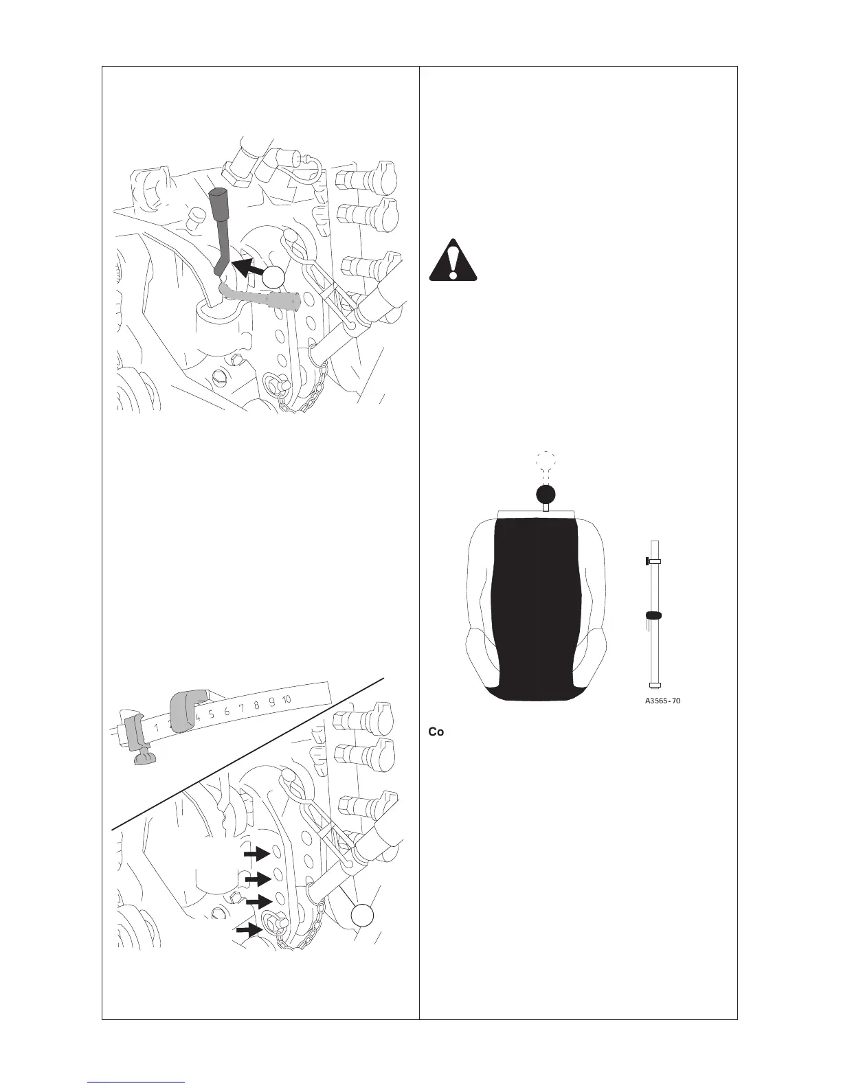
Draft control functions when the impulse sender lever (2)
is in the vertical position.
Set at a suitable working depth for the implement, position
the lever in the locked position. When the draft resistance
exceeds the set value the top link bracket activates the
hydraulic lift which raises the implement so that the
resistance remains constant.
The draft sensing is regulated by the force in the top link.
The automatic weight transmission acts together with the
draft control.
With increasing draft resistance the hydraulic lift raises the
implement and its weight is partly transmitted to the rear
wheels of the tractor so that maximum draft is always
obtained on the rear wheels.
65---44
4
Mechanically controlled hydraulic lift
NOTE: Draft control sensitivity can be altered by
moving the attaching points of the top link (4) on the
tractor. Draft control sensitivity is least when the top
link is connected to the lower hole and greatest when
connected to the upper hole.
Draft control is used when working with soil penetrating
implements (ploughs/plows, cultivators etc).
NOTE: Semi---mounted and fully mounted implements
can not be exploited with top link sensitivity.
WARNING: Only engage draft control with
the lever (2) when there is no load on the
three---point linkage unit (lowest position)
and the position lever is fully in its lowest
position.
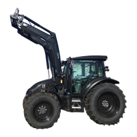
NOTE: Adjust the check links so that the rear end of
the lower links have a play of approx. 70 mm (3 in).
The sideways movement of the implement affects the
draft resistance.
When draft control is not being used the impulse sender
pawl (2) should be in the horizontal position.
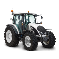
F 4.1.4. Adjustment of lowering speed
A3565--70
Control fully pushed in = max. lowering speed
Control fully pulled out = min. lowering speed
When heavy implements are connected to the hydraulic
lift the lowering speed control should be set at minimum.
This gives the smoothest possible lowering movement.
Free
Locked
Min
sensivity
Max
sensivity