---58---
F. Operating instructions
position and the lower links can then move freely up and
down following the movements of the implement.
NOTE: The control panel is fitted with lights (7) to
indicate whether the lower links are being lifted or
lowered.
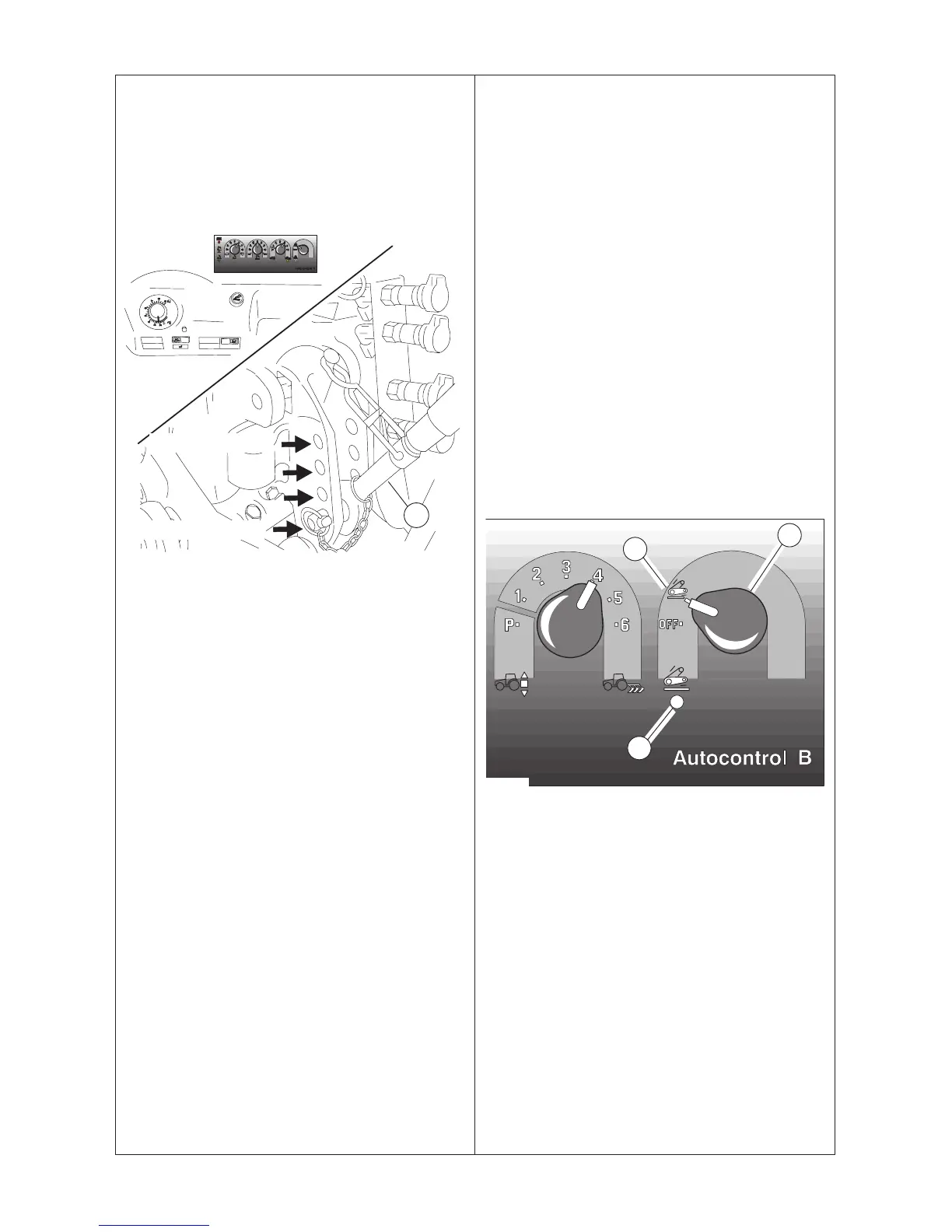
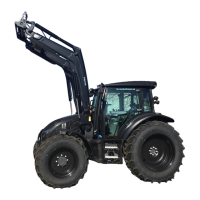
F 4.2.6. Draft control
65---44,1
A
Electrohydraulically controlled hydraulic lift
Draft control is used when working with implements that
operate below the surface of the ground (ploughs/plows,
cultivators etc.). The draft control sensitivity is set by
turning the selector (4) to one of six different sensitivity
positions (1---6). Further the top link (A) can be attached
to four different holes, which give 24 different sensitivity
settings.
On Autocontrol the linkage is adjusted by the draft
controls which influence the working depth, 1 = small
influence ... 6 = very large influence.
NOTE: Semi---mounted and fully mounted implements
can not be exploited with top link sensitivity.
Position 3 or 4 are normally used for ploughing/plowing.
NOTE: The ploughing/plowing depth can be adjusted
using the position control knob (1).
The lift/lower indicator lights (7) show the speed at which
the draft control is operating.
NOTE: The lower links allow a certain amount of
sideways movement to the implement, and this also
affects the range of the draft control. Therefore the
sideways movement of the links should be adjusted to
about 70 mm (3 inches) at the ends of the arms.
NOTE: When draft control is not in use the selector
switch should be turned to the P position.
When the draft resistance exerted by the implement on
the lower links rises to the value set, the linkage lifts the
implement in order to counteract the increase in
resistance trying to keep it constant.
When the draft control is operating the weight of the
implement is automatically shifted to maintain traction. If
pulling resistance increases the hydraulic lift raises the
implement and some of the weight is transferred to the
rear wheels. Thus the driving wheels maintain maximum
traction.
F 4.2.7. Lowering speed control
Choice of lowering speed (5) depends on the type of
implement being used. A slow lowering speed must be
used with heavy implements. The lowering speed is
increased as the knob is turned clockwise and vice versa.
Lowering speed is independent of the load.
F 4.2.8. Passing switch for position control
knob = forced lowering switch
The override switch for position control knob (9) can be
used on jobs, where lower links have to be, temporarily,
lower then the value which has been set by the control
knob. This is useful e.g. when ploughing/plowing. This
switch allows quicker entry of the plough/plow to the
correct depth at the beginning and better maintenance of
depth in exit at the end.
F 4.2.9. Drive balance control switch
A
69---45,2
10
11
The best use of the drive balance control is in driving at
high speed when a heavy implement is attached to the
three---point linkage. It can also be used on fields.
The drive balance control is activated, when the switch
(10) is turned to the position A (indicator light 11 lights).
Then when lifting the linkage with the lift/stop/lower switch
(2), the drive balance control is on.
Min. sensitivity
Max. sensitivity