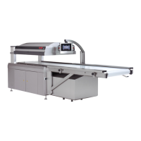
Vacuum Packaging Machine VC999 K7
Description of the machine
2008-11-26 Art.-No. 592.016 Page 17/121
Pre-perforation (24)
The pre-perforation ensures that unusually long bags which protrude from the vacuum chamber lid can
be easily processed. Due to the spring-loaded mechanism on both sides of the vacuum chamber lid, the
bag is pressed together by hold-down clamps when closing the vacuum chamber. The perforation blade
is subsequently released and pressed down onto the bag in the vacuum chamber. This results in small
bag perforations via which vacuum can be created in the bag.
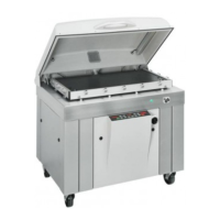
Sealing device (24) with cutter blade (VC999 K7A) or perforation blade (VC999 K7B)
The sealing device consists of two sealing bars in the vacuum chamber lid and two sealing bars in the
vacuum chamber bottom. When the vacuum chamber closes, the upper and lower sealing bars are po-
sitioned opposite each other and pressed together for sealing.
The bag waste is either cut off by a cutter blade (VC999 K7A) or perforated by a perforation blade
(VC999 K7B) during the sealing process. The blades are located in the vacuum chamber lid next to the
sealing bars.
The bags are perforated (VC999 K7B) to ensure that the bag waste can be removed manually once the
bag has left the machine.
Conveyor belt (5)
The conveyor belt runs through the entire Vacuum Packaging Machine. A short run-out roller track (17)
at the end of this belt enables optional conveyor devices to be added on as required by the customer.
The integral initiator ensures that within a packaging cycle the conveyor belt moves far enough for the
packaging product laid between the markings (2, 4) on the feed belt to come to a stop exactly in the va-
cuum chamber.
The conveyor belt can be slackened by means of the tension lever (6) for cleaning and opened for dis-
mantling by removing the plastic wire on the cord at the joint.
Power supply (20)
The electrical (22) and compressed air (23) connections are located inside the machine on the rear wall
of the power supply cabinet (20). The power cable and the compressed air line are fed into the cabinet
from below. The cabinet also contains the compressed air maintenance unit.
 Loading...