34
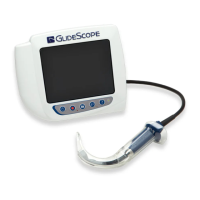
9. If you are completing any of the following procedures,
remove the (8) screws securing the analog PCB
in place (Figure 15):
• Service the Printer
• Replace the Battery Contacts
• Replace the Battery Eject Button
• Replace the Hide or Printer Door
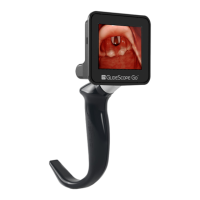
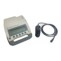
If you are completing any of the following procedures,
remove the (12) or (15) screws securing the entire PCB
assembly in place (Figure 16 or Figure 17):
• Replace the LCD
• Replace the Window or Buttons
• Replace the PCB Assembly
• Replace the Top Cover
• Any combination of service procedures that requires
access to components below both the digital and
analog sides of the PCB assembly.
Notes:
• The number of screws securing the digital PCB to
the window varies depending on the version. PCBs
with a removable EPROM have 7 screws. PCBs with
a built‑in EPROM have 4 screws.
• If you are not replacing the LCD, buttons, or
window, you may unscrew the (7) screws from the
window and then remove the assembled PCB and
attached parts as a unit.
Figure 15. (8) Screws in Analog PCB
Figure 16. (12) Screws Total—(4) in Digital PCB
Figure 17. (15) Screws Total—(7) in Digital PCB
 Loading...