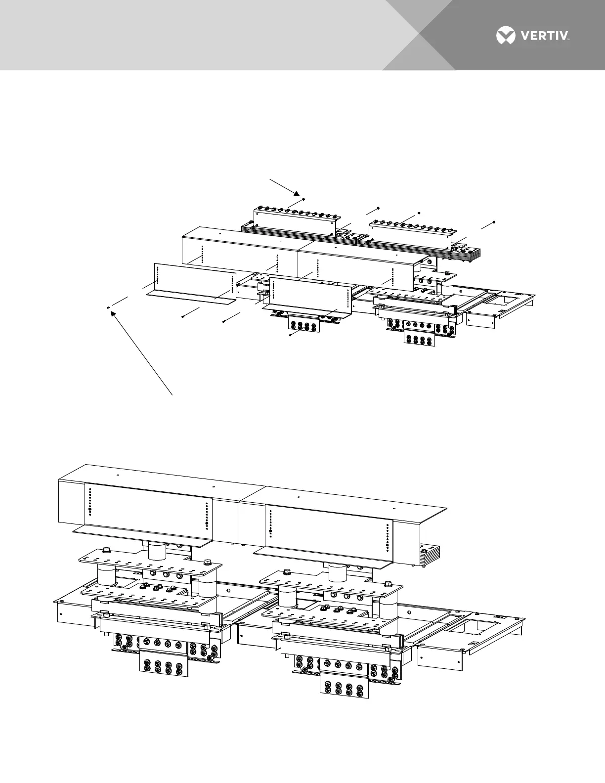
EasyManuals Logo

Vertiv NetSure 8200 Series Installation Manual

Vertiv NetSure 8200 Series
198 pages
To Next Page IconTo Next Page
To Previous Page IconTo Previous Page
Page #76 background imageLoading...
Page #76 background image
Vertiv | NetSure8200 Series -48 VDC Power System Installation Manual (IM582140000) | Rev. A
76
Figure 51:
Power/Distribution Bay Load Return Lug Extension Busbar Assembly (P/N 514543) Assembly
Procedure Step 3B
STEP 3B
Install "Covers"
(List 102 and 112 Bays E/W List 130 or 131 PDSC).
(2*) 10-32 Lock Nut, P/N 104564
(2*) 10-32 x 3/4" Tap Screw, P/N 218706500
* Parts are from the P/N 514690 or 514691 Kit.
Quantities are per Kit, two Kits shown in Illustrations.
The following parts are not used: (2) 1/4-20 x 1/2" Bolt
(P/N 227640200), (2) 1/4" Lock Washer (P/N 215111100),
(2) 1/4" Flat Washer (P/N 214110100)
Rear Top
of Bay
Assembled
View

Table of Contents

Other manuals for Vertiv NetSure 8200 Series

Questions and Answers:

Question and Answer IconNeed help?

Do you have a question about the Vertiv NetSure 8200 Series and is the answer not in the manual?

Vertiv NetSure 8200 Series Specifications

General IconGeneral
BrandVertiv
ModelNetSure 8200 Series
CategoryPower Supply
LanguageEnglish

Related product manuals