Vertiv | SmartCabinet | User Manual 41
System Installation
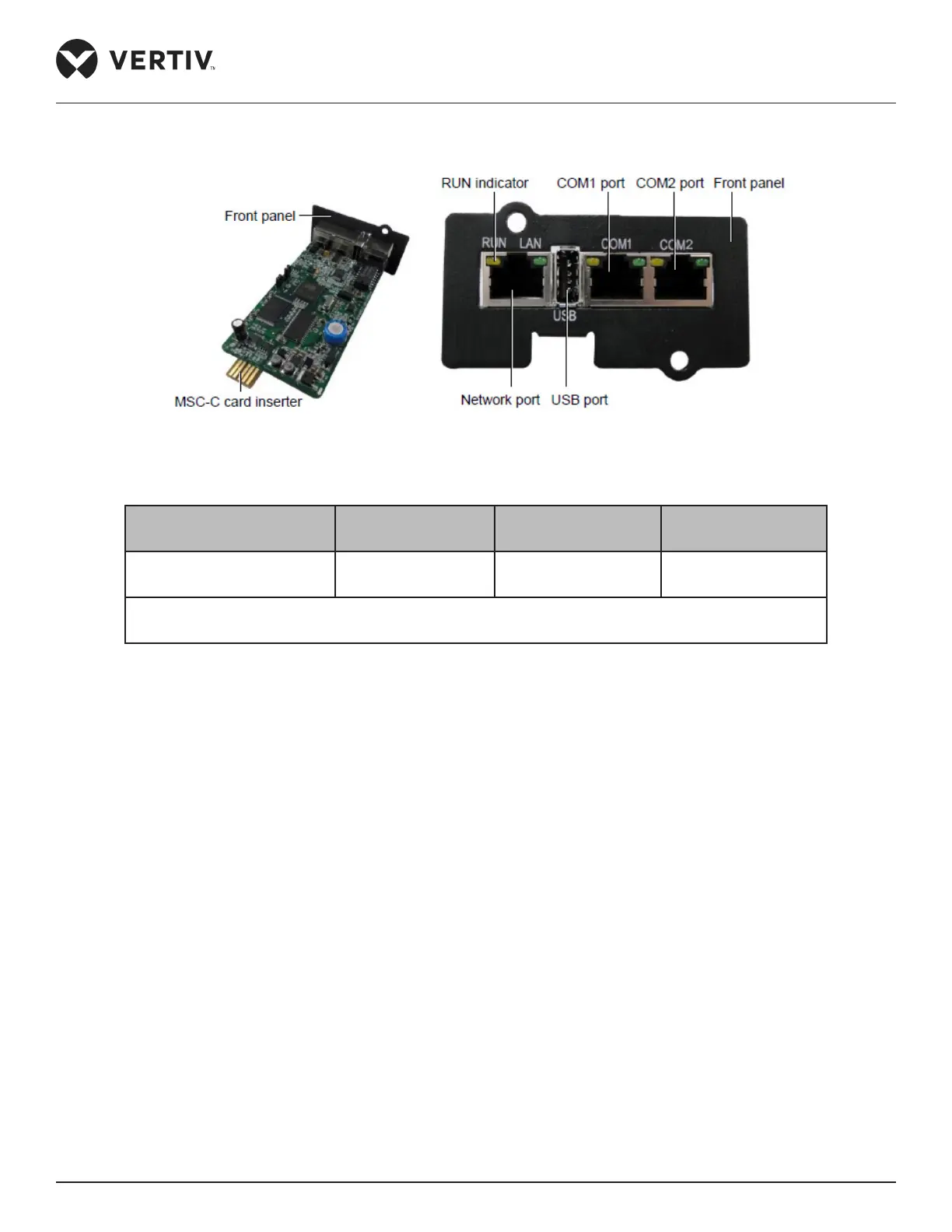
Figure 2-31 shows the real-time image of the MSC monitoring card.
Figure 2-31 Appearance of the MSC intelligent monitoring card
Table 2-12
Connected Component Cable Standard
Connected distance
(unit:m)
Connected number /
Connected point
Port to connecting node Twisted pair cable of
standard category 4
≤ 100 8*
Note*: All the intelligent devices connect to COM2 of MSC intelligent monitoring card, and a
maximum of 8 devices can be serially connected
The following cautionary measures need to be observed to avoid personnel injury and prevent equipment
damage:
• Prior to any installation operation on the MSC monitoring card, always cut o the power.
• Ensure that the external devices are connected properly to the correct MSC card ports.
• Wear an ESD wrist wrap during installation.
• Arrange the wires appropriately. Do not place any heavy objects on the wires or stamp on them.
• The jumpers need to be set to the correct position. The jumper locations are shown in Figure 2-31.