D-303222 PowerMaster-10 / PowerMaster-30 Installer's Guide 9
2. INSTALLATION
2.1 Choosing the Mounting Location
To ensure the best possible mounting location of the PowerMaster-10 / PowerMaster-30 control panel, the
following points should be observed:
• Mount the system approximately in the center of the installation site between all the transmitters
• In close proximity to an AC source and a telephone line connection (if PSTN is used)
• Far from sources of interference, such as:
electrical noise and strong electromagnetic sources, such as computers, television, power conductors,
cordless phones, light dimmers, etc.
large metal objects (such as metal doors and metal closets)
Note: A distance of at least 1 meter (3 ft) is recommended.
• Make sure that the signal reception level for each transmitter's signal, shown during the Diagnostics test of
the PowerMaster-10 / PowerMaster-30, is "Strong" or "Good".
• The alarm can be heard during HOME mode.
• Wireless magnetic contacts should be installed in a vertical position and as high up the door or window as
possible.
• Wireless detectors should be installed at the height specified in their Installation Instructions
• Repeaters should be located high on the wall in mid-distance between the transmitters and the control panel.
WARNING! To comply with FCC and IC RF exposure compliance requirements, the control panel should be
located at a distance of at least 20 cm from all persons during normal operation. The antennas used for this
product must not be co-located or operated in conjunction with any other antenna or transmitter.
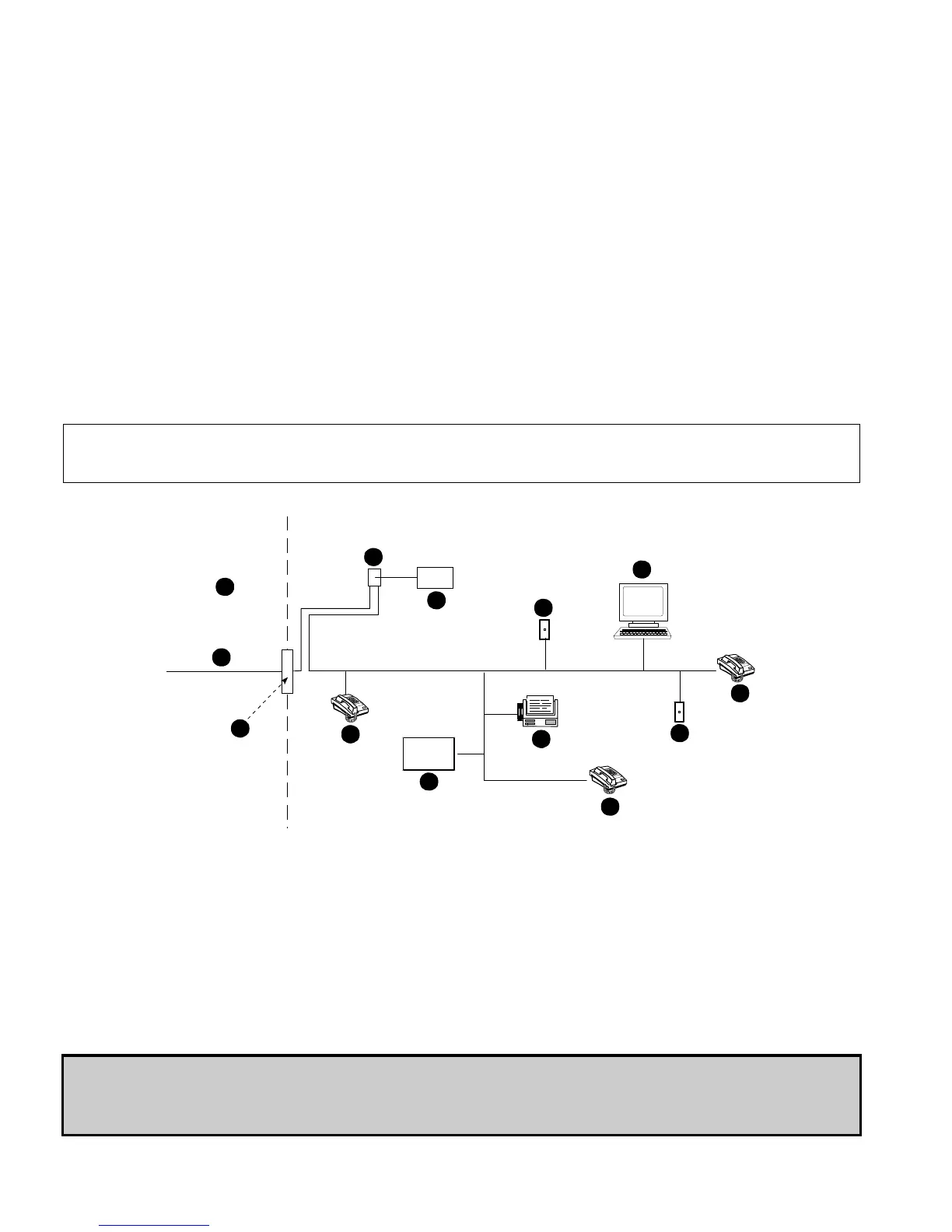
Customer Premises Equipment And Wiring
A
B
C
D
E
F
G
H
I
E
E
H
J
A. Network Service Provider's Facilities F. Alarm Dialing Equipment
B. Telephone Line G. Answering System
C. Network Demarcation Point H. Unused RJ-11 Jack
D. RJ-31X Jack I. Fax Machine
E. Telephone J. Computer
Note: The REN is used to determine the number of devices that may be connected to a telephone line. Excessive
RENs on a telephone line may result in the devices not ringing in response to an incoming call. In most but not all
areas, the sum of RENs should not exceed five (5.0). To be certain of the number of devices that may be
connected to a line, as determined by the total RENs, contact the local telephone company.
Connection to telephone company provided coin service is prohibited. Connection to party lines service is
subject to state tariffs.
The installer should verify line seizure. Be aware of other phone line services such as DSL. If DSL service is
present on the phone line, you must install a filter. It is suggested to use the DSL alarm filter model Z-A431PJ31X
manufactured by Excelsus Technologies, or equivalent. This filter simply plugs into the RJ-31X jack and allows
alarm reporting without breaking the internet connection.