D-303222 PowerMaster-10 / PowerMaster-30 Installer's Guide 11
2.2.2 Closing the PowerMaster-10 Control Panel
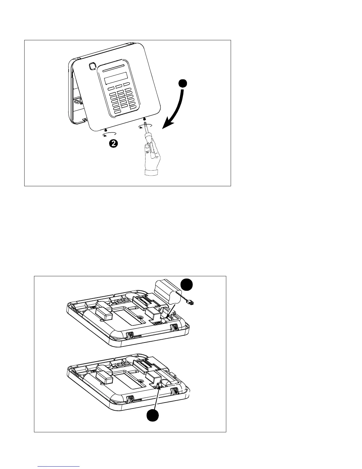
Control panel final closure is shown below.
1
Figure 3.2 - Final Closure
To Close the Control Panel:
1. Close the front cover
2. Fasten the screws
2.2.3 Supplying Power to the Unit
Connect power to the PowerMaster-10 temporarily (see Figure 3.3). Alternatively, you may power up from the
backup battery, as shown in Figure 3.3.
Disregard any “trouble” indications pertaining to lack of battery or lack of telephone line connection.
For Europe Safety Compliance:
a. The model shall be installed according to the local electrical code.
b. The circuit breaker shall be readily accessible.
c. The rating of the external circuit breaker shall be 16A or less.
d. The cables for the AC mains connection shall have an overall diameter of 13mm and 16mm conduit.
Please refer to Figure 3.3 "Power Cable Connection".
1
2
Figure 3.3 – Connecting Power to the Control Panel
Inserting Backup Battery:
Connect battery pack as shown in
Figure 3.3.
1. Insert battery
2. Connect the battery