22 D-303222 PowerMaster-10 / PowerMaster-30 Installer's Guide
2.3.2 Closing the PowerMaster-30 Control Panel
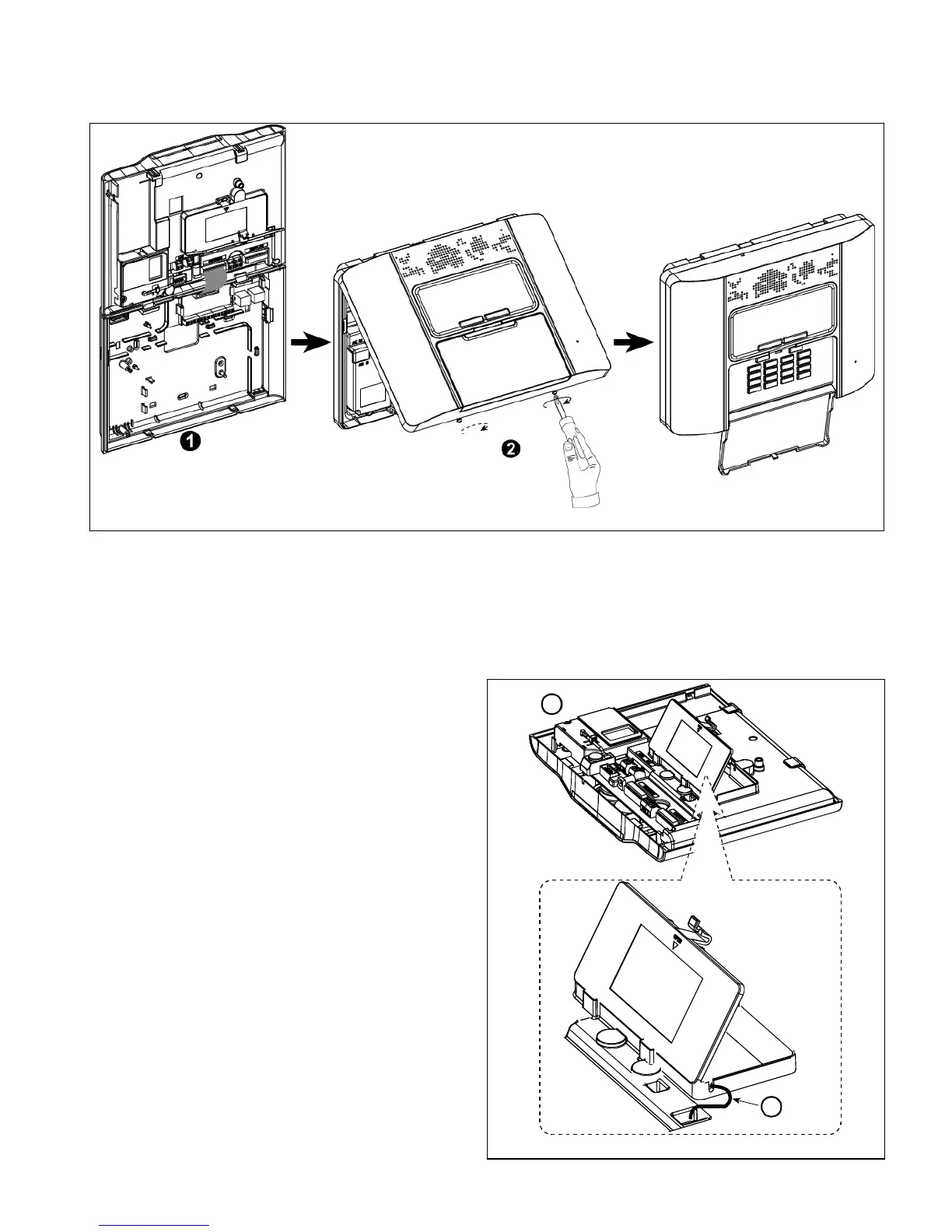
Control panel final closure is shown below.
Figure 3.14 - Final Closure
To Close the Control Panel:
1. Connect the flat cables, between front and back units, in their respective connectors (up to 3, according to options).
2. Close the panel and fasten the 2 screws.
2.3.3 Supplying Power to the Unit
Connect power to the PowerMaster-30 temporarily (see Figure 3.23). Alternatively, you may power up from the
backup battery, as shown in Figure 3.15.
Disregard any “trouble” indications pertaining to lack of battery or lack of telephone line connection.
Open battery compartment cover (see Figure 3.15).
Insert one 6-battery pack or 8-battery pack and
connect its connector as shown in Figure 3.15.
A. Front unit
B. Battery cable
A
B
Figure 3.15 – Battery Insertion