D-303222 PowerMaster-10 / PowerMaster-30 Installer's Guide 13
2.2.5 System Planning & Programming
It pays to plan ahead - use the tables in APPENDIX D. Detector Deployment & Transmitter Assignments and
APPENDIX E. Event Codes at the end of this guide to register the intended location of each detector, the holder
and assignment of each transmitter.
Gather up all transmitters and detectors used in the system and mark each one in accordance with your
deployment plan.
Program the system now, before mounting, as instructed in the programming section.
2.2.6 GSM Module Installation
The internal GSM 350 module enables the PowerMaster-10 system to operate over a GSM/GPRS cellular
network (for further details, see the GSM 350 PG2 Installation Instructions).
The GSM modem auto detection feature enables automatic enrollment of the GSM modem into the
PowerMaster-10 control panel memory. GSM modem auto detection is activated in one of two ways: after
tamper restore and after reset (power-up or after exiting the installer menu). This causes the PowerMaster-10 to
automatically scan GSM COM ports for the presence of the GSM modem.
In the event that the GSM modem auto detection fails and the modem was previously enrolled in the
PowerMaster-10 control panel, the message "Cel Rmvd Cnfrm" will be displayed. This message will disappear
from the display only after the user presses the
button. The modem is then considered as not enrolled
and no GSM trouble message will be displayed.
Note: A message is displayed only when the PowerMaster-10 alarm system is disarmed.
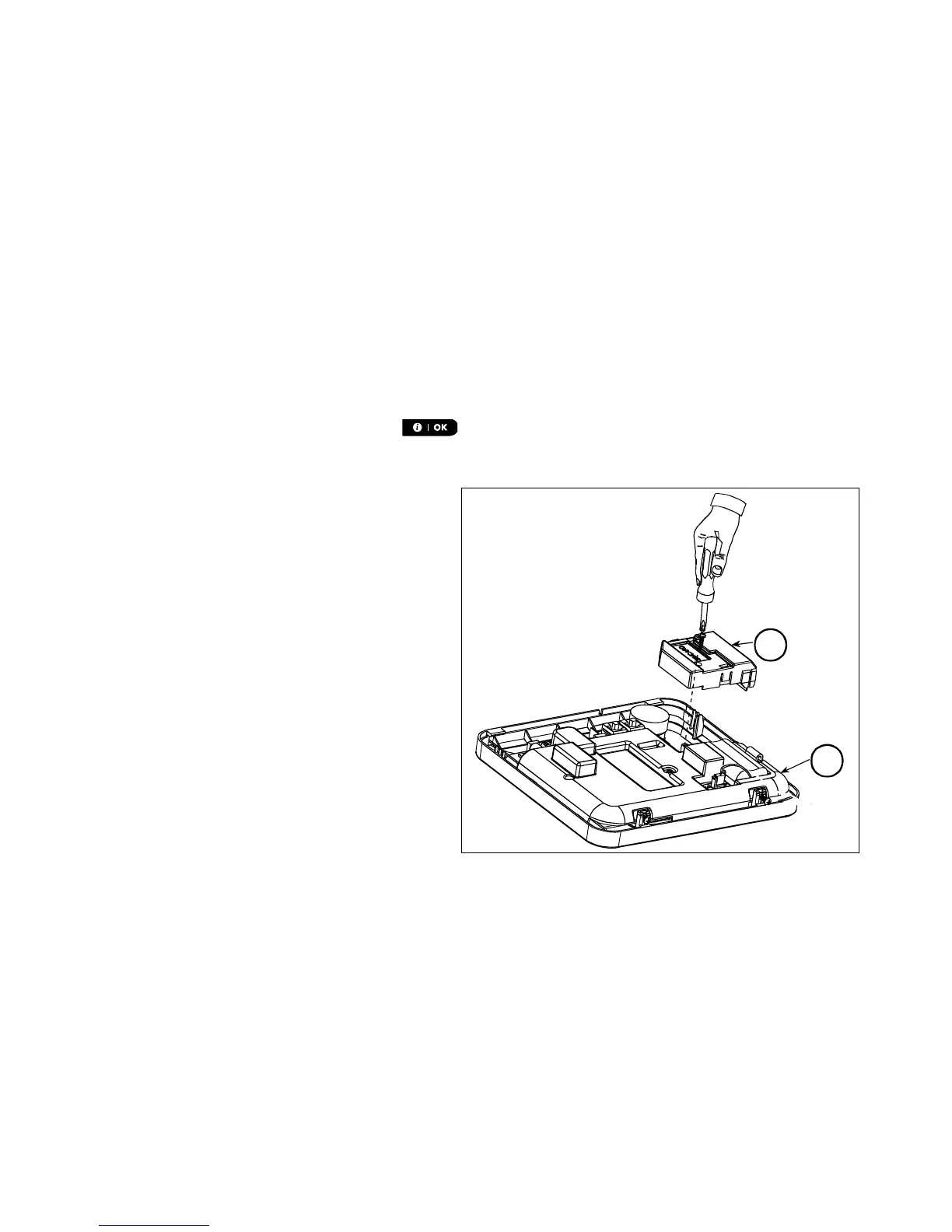
Plug in the GSM module and fasten it as shown in
Figure 3.5.
A. GSM
B. Front unit
A
B
Figure 3.5 –Optional GSM Module Mounting