EasyManuals Logo

Visonic POWERMASTER 10 Installer's Guide

Visonic POWERMASTER 10
106 pages
To Next Page IconTo Next Page
To Previous Page IconTo Previous Page
Page #16 background imageLoading...
Page #16 background image
D-303222 PowerMaster-10 / PowerMaster-30 Installer's Guide 15
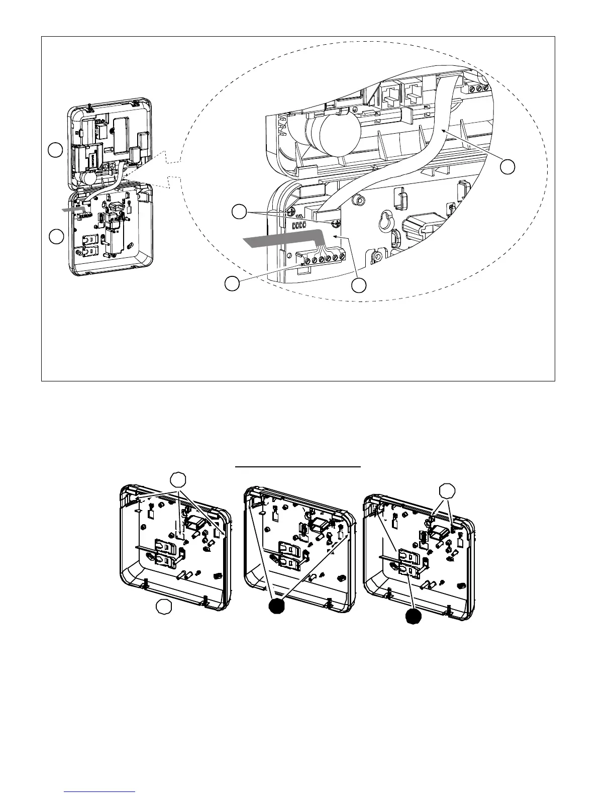
B
A
C
D
E
F
A. Front unit
B. Back unit
C. PGM-5 Module
D. 2 Screws for fastening the PGM-5 Module
E. Flat cable
F. Wiring
Figure 3.7 – PGM-5 Module Mounting
2.2.8 Adding Wired Zones or PGM
Required tools: Cutter and slotted screwdriver - 3 mm blade.
PowerMaster-10 wiring is shown in Figures 3.8 – 3.11.
CABLES ROUTING GUIDE
1
A
B
2
C
A. Cables entry options
B. Back unit
C. Cable clips
To Route the Cable:
1. Remove the left or right side cables entry knockout(s) and enter the required cable(s)
2. Remove and use as cable clamp(s)

Table of Contents

Other manuals for Visonic POWERMASTER 10

Questions and Answers:

Question and Answer IconNeed help?

Do you have a question about the Visonic POWERMASTER 10 and is the answer not in the manual?

Visonic POWERMASTER 10 Specifications

General IconGeneral
Communication ProtocolsPowerG
Frequency433-434 MHz, 868-869 MHz
System TypeWireless
CommunicationGSM
Remote ControlYes
Event Log1000 events
Partitions3
Humidity85% non-condensing
User Codes8
Backup BatteryNi-MH battery pack
Operating Temperature-10°C to +50°C

Related product manuals